This is going to be a quick post (compared to the average post here).
I recently was in need of a USB to MIDI adapter, wanted to test a midi implementation on a ATmega8 and also check out VCV Rack with my keyboard, which is pretty old and only has a legacy MIDI connection. I didn’t have a USB to MIDI adapter, and was not so keen to buy one anyways, so I set out to find the easiest USB MIDI implementation I could build in a afternoon.
Later, after some searching, I found this project by Yoshitaka Kuwata on the V-USB website. It is a USB MIDI IN and OUT adapter running on an ATtiny micrcontroller, as expected, by making use of V-USB. With some tweaking I could modify the code to run on a USBASP.
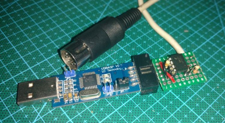
If you have not been introduced, the USBASP is an AVR programmer. Therefore, it is used to load code into AVR microncotrollers, like the Atmegas used on Arduinos. It uses V-USB, a software implementation of USB, as the ATmega8 it uses does not have native USB. I have used it as a USB adapter for SNES controllers before. They are very cheap, going as low as two US dollars or less on eBay. A good thing is that the serial (UART) pins, needed by the Legacy MIDI protocol, are already broken out to the connector.

USBASP schematic
The original code was a bit outdated, being updated for the last time in 2014. I replaced and reconfigured V-USB to the last version available on their website. I also fixed the code to run, and make use of the correct pins, on a ATmega8 instead of an attiny2313. That is it, all the credit goes to Yoshitaka. To burn the code into a USBASP with another, I just connect the ICSP cable between the two and close the jumper JP2 on the target board. See below, the programmer at the top is the target (JP2 closed).
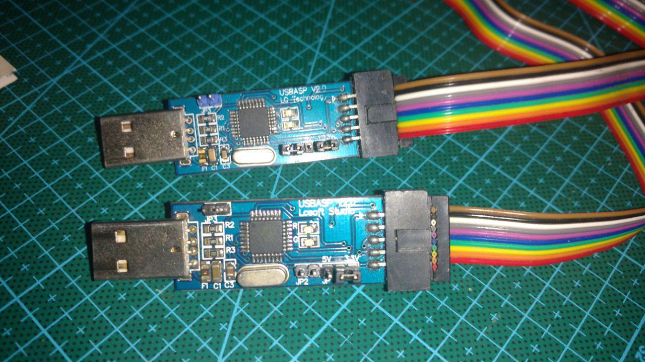
I have three of these programmers, because I keep losing them on my stuff. So when I need one, I just use the first I find. It is okay, they are super cheap and last forever. I still have the first one I bought in 2013.
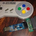
I could not hook up the MIDI port directly to the ATmega8. The MIDI implementation is isolated, so I used a 6N137 opto-isolator for the job. If you are going to try this, have in mind that you need an appropriate opto-isolator, with fast raising and falling times. I have had no problems with the 6N137. The circuit I used is quite simple, and can be seen below. Thankfully I had all the components here already, including some 5 pin DIN connectors, so I did not have to destroy a MIDI cable or anything like that.
 I am not using MIDI OUT, although it is supported by the code and microcontroller. If you need it, you can easily find schematics online, usually with inverters, just tie the input of the circuit to the TX pin on the header.
I could make a board layout and mill it on the CNC, bit it was too much of a hassle for something so simple. So I just used some veroboard. I works fine, but it is ugly as hell. It fits into the programming header, so I can remove it when I need to use the programmer for programming or probably anything else.

Well, what can I say? It works. I am sharing this here so anyone with the same problem and a spare USBASP can save some time. Hope I can still use legacy MIDI for some time, as it is easy to program into a microcontroller. Recently I was searching and could not find a compact MIDI controller with legacy MIDI, most of them only have USB.

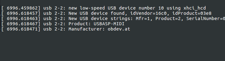
Oh. I should mention that I don’t know how to play the keyboard (or any instrument whatsoever) yet, and because of this I won’t record a test video. I got started into music through electronics, and although I can (slowly) read sheet music and understand some concepts of synthesis (even FM), I have not practiced enough to play anything. You unfortunately will have to take my word on this one, haha. The dmesg output for the device connection can be seen below:
Well, that is it, I guess. The code can be found on my github.
Thanks for reading. See you next post o/


Thanks for sharing..
Thanks for reading!
This looks like a really great way of cheaply getting usb to work with MIDI
As i’m a noob with programming do I need to use say ATMEL studio to create a .hex file to program the chip. Or is there an easier way to do this. I have a USBASP and will buy another to try.
many thanks
HI Glynn
I guess you may be able to use Atmel studio to compile the code, but that may be a chore to set up. I use just bare AVR-GCC on Linux, so unfortunately I can not help with that.
However, I have added the already compiled .hex file to the repository, you can burn that with avrdude or a similar program.
Thanks for reading!
what is about the driver?
Hi Rosyd
Sorry I did not make that clear.
USB HID (Human Interface Devices) devices don’t need new drivers, just like a mouse or keyboard. The system (wether linux or windows or whatever really) already has the drivers for this class of USB devices.
Robson
hi Robson , and how to set fuses?
Hey robson, do you think this code could be used/adapted on an arduino nano? (atmega 328p)
I’ve been trying to look at the code but i can’t figure out where the pins are declared, to set them to the pins i’d use on the nano
Hi Psy.
Kinda, but…
It’s been a long time and I’m sure there are so many better ways of doing this now.
You probably can use a pro micro, which already has (true) usb and another library.
Doing this with an Arduino can be a bit troublesome. The USB connector on the nano is connected to an USB to serial converter and not to the microcontroller itself. So you’d have to add that externally with the diodes and resistors needed. Also compiling a pure C project is not straightforward as using arduino code.
To answer your other question, the pins are declared in usbconfig.h. That is pins 0 and 1 of PORTB.
Yeah, i just suggested the nano since i have some of those laying around, since my mates keep burning their diodes and ch340g serial/ttl/uart IC’s, so they’re basically free atmega328p’s on breakout boards for me lol, i program them with an arduino uno, tho i do also have a mint condition nano
and, yeah i wasn’t expecting to use the mini usb port in the nano
also, after commenting i did figure out how to declare the D+ and D- pins in usbconfig.h
i just don’t know where the pins are defined for the midi in and out, are those always the RX and TX pins in the microcontroller or is there a pin number somewhere i have to set?
The uart (serial) is configured in main.c
/* set baud rate */
UBRRH = 0;
UBRRL = 23; /* 312500Hz at 16MHz clock */
/* */
UCSRB = (1<
That is, pins 0 (RX) and 1 (TX) of the PORTD. Which I believe are the same pins for the Atmega328.
aw, now i’m getting all sorts of errors trying to run “make hex”
https://imgur.com/a/KocGVhU
not sure if it’s too much of a problem/you’re too busy to help me?
I can not think of anything else other than have you installed avr-gcc and avrlibc?Specially the latter, since it can not find the respective source files (and thus registers) for atmega328 in your snapshot
Eh, nevermind
I also tried using the atmega88 fork of your github repo, which after doing the same changes DID end up compiling, and i was able to upload it and everything
But i get error 43 when plugging the usb cable in, so i’m not sure if there’s something wrong with how i changed the dminus but to 6 and dplus to 7… maybe i need to change the port from PORTB to something else?? not sure how that works honestly
I keep getting that error without the arduino there so it might be my zener diodes clamping the voltage too low even tho they’re rated for 3.6v (i have pins 6 and 7 wired off the atmega the same way the schematic for the usbasp you posted has them, 68 ohm resistor, 3.6v zeners and stuff, pull up resistor on dminus (2.2k), and i actually get 3.11 volts when i put 5v where pins 6 or 7 would be on the board instead of 3.6 or 3.3, so idk what else to do other than try getting zener diodes from some other manufacturer, or maybe try other resistor values like 18 ohm instead of 68
i might just give up and buy that usbasp programmer
Nevermind my other comment lol, i got it working
Was something weird with how i had the usb cable going to the 5V pin instead of VIN, for some reason it doesn’t work when being powered from the 5V pin
So i just grabbed the atmega88 fork since that one works, and in the makefile i changed the hz to 16000000, DEVICE to atmega328p
Then in usbconfig.h i set USB_CFG_IOPORTNAME to D, USB_CFG_DMINUS_BIT to 4 and USB_CFG_DPLUS_BIT to 2
ran “make hex” and uploaded/programmed my nano with that
Works! (or at least it gets recognized by windows, i gotta test it with my keyboard at home)