Some time ago, we were approached by PCBway about getting sponsored PCBs for review. I actually got pretty hyped, as I never had sent a PCB to be manufactured before. Even tough I have designed some PCBs for milling at home, they have to be very simple.
A little background, almost everything I write here are personal projects, at the moment I work as a firmware developer, but I like to learn about hardware on my spare time.
This would also be an opportunity to test my skills at Altium. I have used Eagle and Proteus for designing stuff for college classes and my projects, but I have known that Altium is supposed to be a more professional tool and a little harder to get into. Also, the hardware people use it at work as well, so I could get a few tips from them.
Project
The board I chose to build was a WiFi connected digital clock. I had already poorly built one that we use at home, so I already had the firmware. The displays I used were 5V, 4,8cm (or 1.8 inch) tall seven segment displays. The clock uses an esp8266 microcontroller and gets its time from the network using the NTP protocol. It can be powered by a 5V USB adapter.
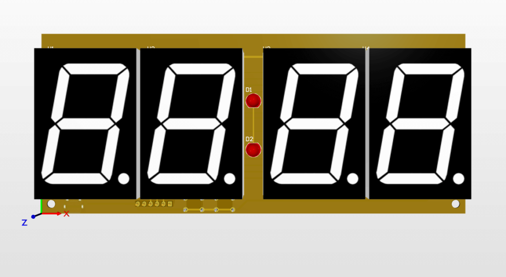
I drew the seven segment displays, and max7219 footprints/models. Unfortunately I got the ESP12 model online and it caused me some trouble later.
At some point while I was designing the board, I accidentally deleted the two mounting holes at the top. So they are not in the PCBs I received as well.
Printed Circuit Boards
The PCBs were made in 3 days if I am not mistaken. I deliberately chose e-packet as delivery method, and received the boards in 20 days. That is pretty quick for receiving international international packages where I live.
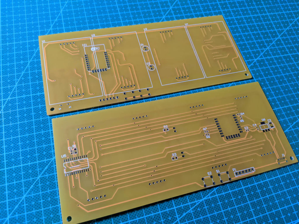
The traces are looking very good and the vias are tented as I wanted. The soldermask and silkscreen are very sharp, plus I loved the yellow color. Overall I am really satisfied with the quality. Still, this was a very simple circuit. I will try to up my skills a little and try something more complicated next time.
Soldering
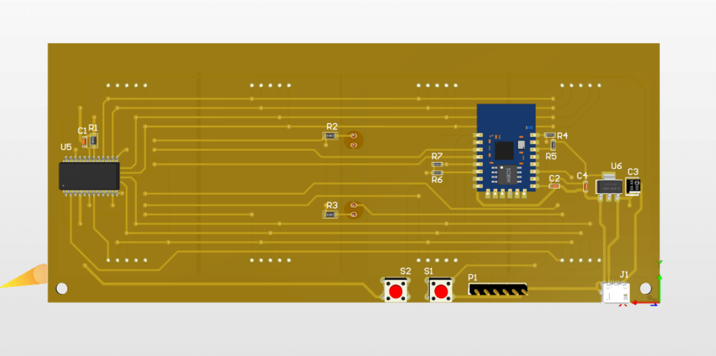
I tried soldering one of the boards, but I only had components for one. I soldered the ESP12 module on as it is showed in the 3d model of the board, without checking the pinout during design or even during soldering.
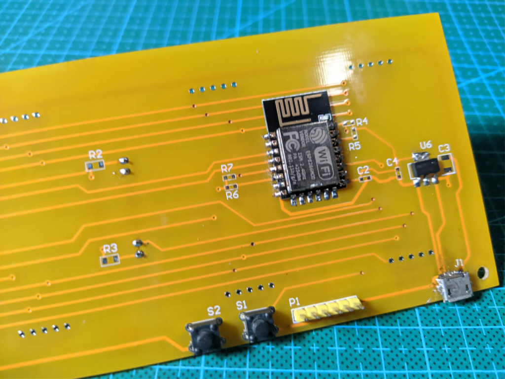
After a little test with a few ICs soldered, I noticed that the regulator was getting hot. I checked and the esp8266 was soldered backwards. It could work if I had mounted on the other side of the board. This is what I get from downloading models from the internet without double checking them.

Unfortunately I only had components for building a single board, otherwise I could solder another. Since USD skyrocketed as Brazil is going through a lot and there is also some problems with shipping, this may take a while. I will have to order new components when possible and then create a new post explaining the pcb design and MCU firmware.
Conclusion
I am quite happy with the first board I designed in Altium, it is missing some mounting holes and the ESP12 footprint was messed up, but the boards are totally usable. Unfortunately I did not have the components to build a second board, but I will order new parts to finish these boards as soon as possible. Finally, I would like PCBWay for sponsoring this project, I am quite happy the the boards’ quality.