
Intro
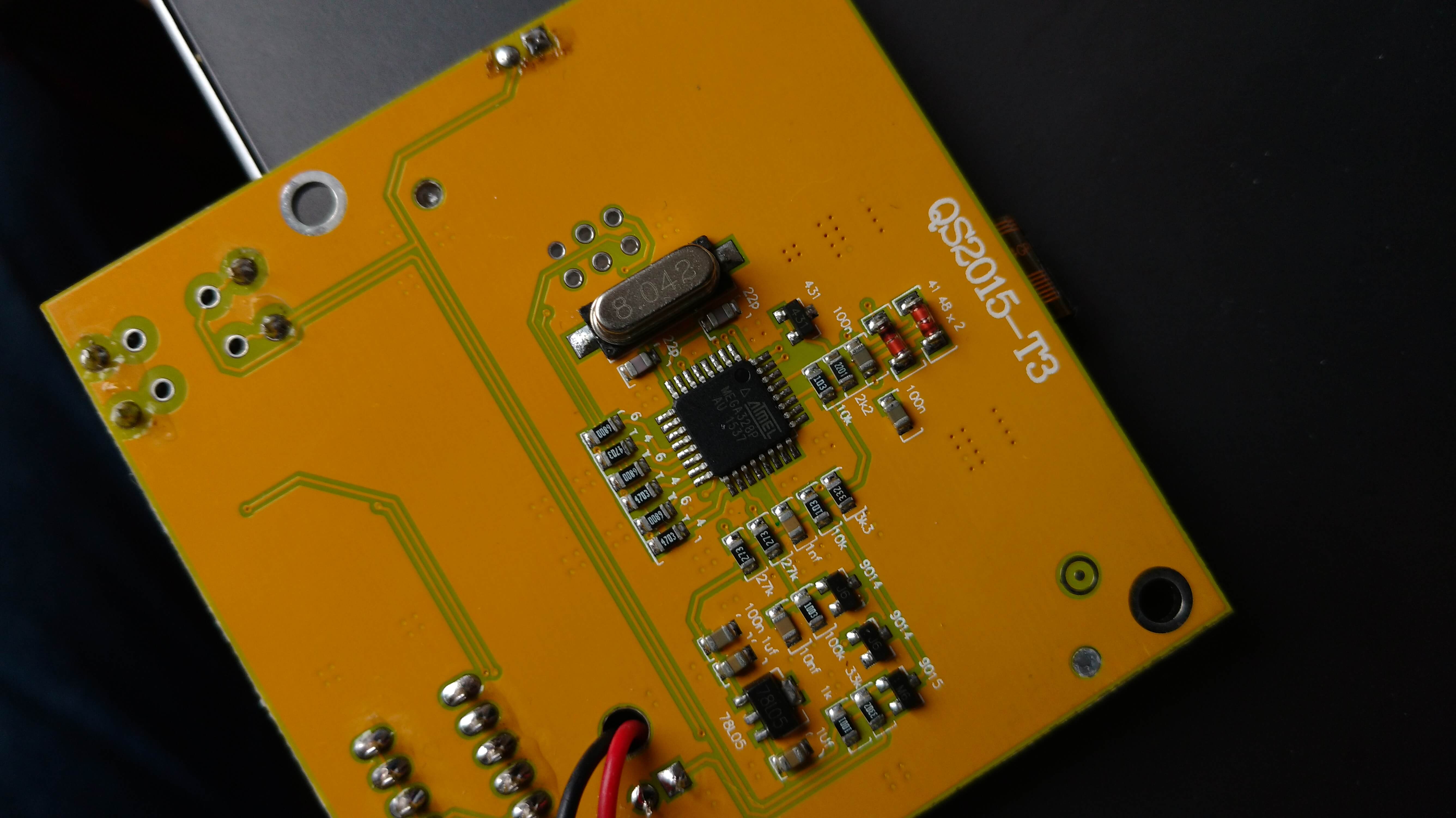
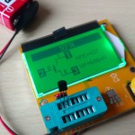
Some time ago I got one of these transistor testers on eBay for around 10$. It is quite useful, specially because my multimeter does not measure capacitance or inductance. I did a samll write up about it in portuguese here. First thing I noticed was the popular Atmega 328p on the back of the board.
For some reason, I tried to calibrate it (there was no need) and messed up the values. Whatever was wrong, was inside the chip, specifically inside the chip’s eeprom. I found a way to read and program the chip, and then tried erasing the eeprom using avrdude, but could not get the measurements right. This made me think the board already comes calibrated from the seller. Because it was so easy to program the chip, I had decided that if I could not get it working I would just use it for anything else. I turns out I was just using a small capacitor when calibrating it, after using a capacitor of higher value than the recommended it worked just fine.
Anyways, the atmega328p used on the board it is the same present in many duinos out there(UNO, Nano, Mini, a thousand clones.. etc), so it got me thinking “Why something so hackable is not being hacked?”. I mean, it has an LCD screen, a sort of button, battery connection, and a SPI port available.
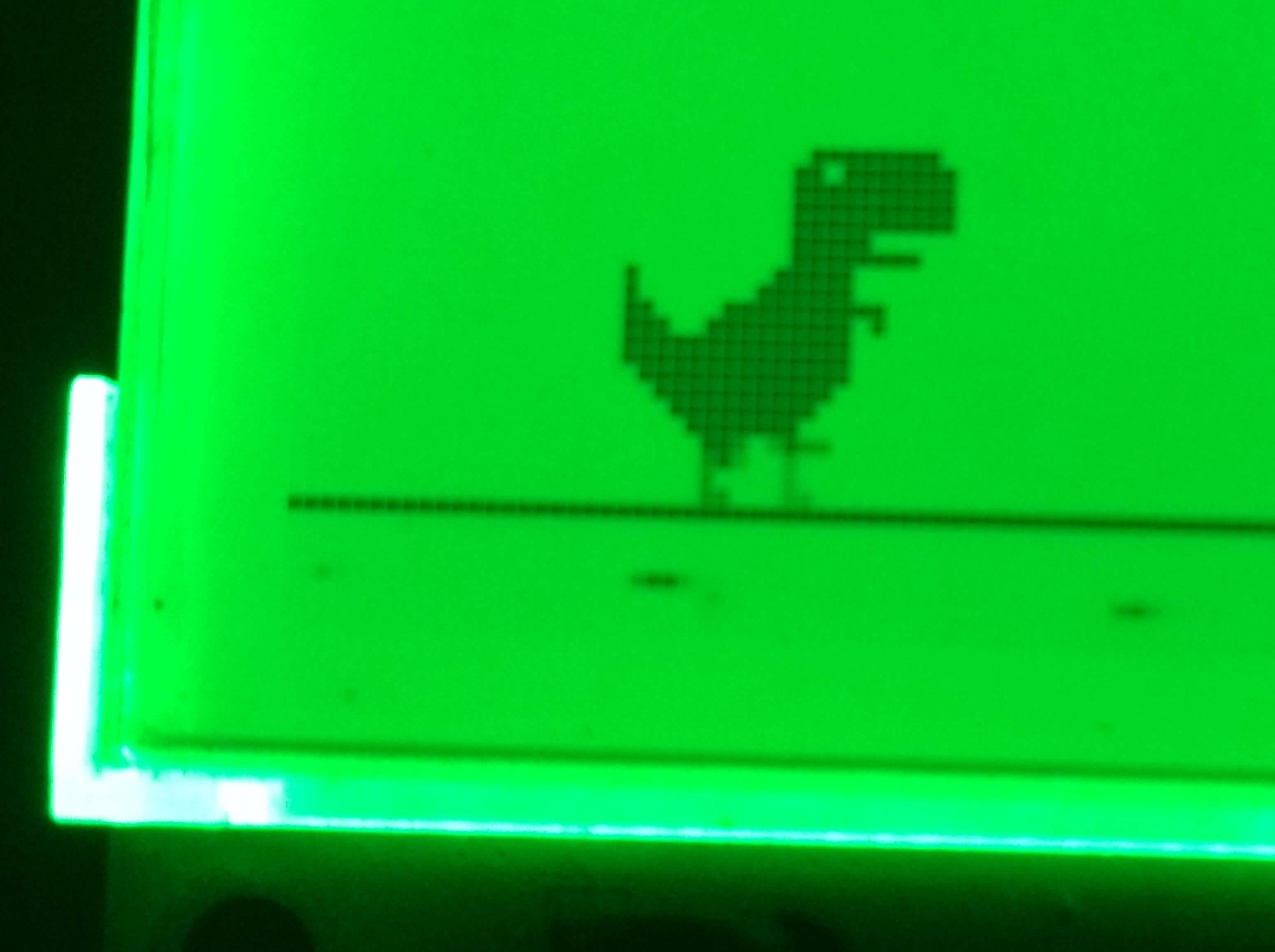
Following, I will explain how I got the component tester to run a game similar to the T-Rex game. It is far from good, but I learned some tricks along the way. As this is my first try at something game/graphics stuff, I had a lot of guessing. Suggestions are welcome!
First, some reverse engineering
Started this project last July. But only now I got free from college(summer in Brazil) and had time to finish and document it. Some information here can be just a bit inaccurate, but don’t worry I got a sort of good memory :)
I knew the board was based on a open source project by Markus Frejek. But as there were so many versions I did not believe that the original repo would contain files for my tester, so I set out to find out the LCD reference and pinouts.
Searching on-line I read that a LCD that matches the one (in size and look) on the board was based on the ST7565 controller, but first I had to know which pins of the atmega connected to the LCD.
By simply using a multimeter and the continuity test, I was able to find out that the LCD was connected to PORTD of the microcontroller. But how would I know which pin from the microcontroller is connected to each pin of the LCD(IO,RESET, CLK and so on) if I could not find its pinout?
The best way, I thought, would be having a look at the disassembly of the current firmware, that is, if it was available.The flash was not protected and I could read the flash without problem. I used ODA to disassembly the binary. There is a ‘reversed’ ISCP on the board, so I did not have to solder any wires in order to read the chip. See in the picture below how I connected my trusty USBASP to the Atmega.

Before anything, I dumped the original firmware. I just burn this file to the board again when I want to use it as a transistor tester.
avrdude -p m328p -P usb -c usbasp -U flash:r:firmware.bin:r
And simply used ODA for disassembling the file.
But now that I have the old firmware disassembled, what were I looking for here? Quite easy, by looking for writes to the address of PORTD, eventually I would find the pins used as a the SPI. The mega328p hardware SPI is in PORTB, so the GPIOs on PORTD were bitbanging the data to the LCD as a software SPI.
Lets have a look at this table from the microcontroller Datasheet

From the table, PORTD address is 0x0B when not using LD or ST istructions. Searching this address in the disassembly I found the following code:
.data:00000a5e 66 23    and    r22, r22      ;Depending on the value of r22, does sbi or cbi.
.data:00000a60 11 f0    breq    .+4            ;  0x00000a66
.data:00000a62 5b 9a    sbi    0x0b, 3    ; 11  ;command/data line?
.data:00000a64 01 c0    rjmp    .+2            ;  0x00000a68
.data:00000a66 5b 98    cbi    0x0b, 3    ; 11
.data:00000a68 90 e0    ldi    r25, 0x00    ; 0
while:
.data:00000a6a 5a 98    cbi    0x0b, 2    ; 11
.data:00000a6c 87 ff    sbrs    r24, 7      ;Skip if Bit in Register is Set. Doesn't change the line? Maybe data line?
.data:00000a6e 02 c0    rjmp    .+4            ;  0x00000a74   ;jump and does not set bit
.data:00000a70 59 9a    sbi    0x0b, 1    ; 11  ;set bit. Maybe data line
.data:00000a72 01 c0    rjmp    .+2            ;  0x00000a76   ;
yes:
.data:00000a74 59 98    cbi    0x0b, 1    ; 11  ;clear bit depending on r24
.data:00000a76 5a 9a    sbi    0x0b, 2    ; 11  ;plossibly clock line
.data:00000a78 9f 5f    subi    r25, 0xFF    ; 255    ;subtract immediate r25=r25-0xFF (???)
.data:00000a7a 98 30    cpi    r25, 0x08    ; 8        ;compare with immediate
.data:00000a7c 11 f0    breq    .+4            ;  0x00000a82   ;escape
.data:00000a7e 88 0f    add    r24, r24
.data:00000a80 f4 cf    rjmp    .-24           ;  0x00000a6a   ;while?
.data:00000a82 08 95    ret


r22 is only passed with a value of 0x00 or 0x01, A great chance it is a cmd/data line

Example
.data:00000c14 8a ea    ldi    r24, 0xAA    ; 170
.data:00000c16 60 e0    ldi    r22, 0x00    ; 0
.data:00000c18 0e 94 2f 05 call    0xa5e    ;  0x00000a5e

I suspect r24 is the main value passed to the routine
From this I got that:
a0           PORTD3
clock        PORTD2
data         PORTD1
And from other parts of the disassembly:
reset        PORTD4 //only called at the start of LCD
cs           PORTD5
That is awesome, and I got kind happy for figuring it all by myself, but some days later I found the following piece of code in file config.h from the open source repo:
/*
 *  Chinese clone T3/T4 with ST7565 display
 *  - thanks to tom666 @ EEVblog forum
 */

#if 0
#define LCD_ST7565R_SPI
#define LCD_GRAPHIC                     /* monochrome graphic display */
#define LCD_PORT         PORTD          /* port data register */
#define LCD_DDR          DDRD           /* port data direction register */
#define LCD_RESET        PD4            /* port pin used for /RES */
#define LCD_A0           PD3            /* port pin used for A0 */
#define LCD_SCL          PD2            /* port pin used for SCL */
#define LCD_SI           PD1            /* port pin used for SI (LCD's data input) */
#define LCD_CS           PD5            /* port pin used for /CS1 (optional) */
#define LCD_DOTS_X       128            /* number of horizontal dots */
#define LCD_DOTS_Y       64             /* number of vertical dots */
#define LCD_START_Y      0              /* start line (0-63) */
#define LCD_CONTRAST     11             /* default contrast (0-63) */
#define FONT_8X8_V                      /* 8x8 font, vertically aligned */
#define SYMBOLS_24X24_V                 /* 24x24 symbols, vertically aligned */
#endif
Great, all the previous work for nothing. As my friend Márcio used to say “A lot of work is wasted”.
Getting the LCD to work
Ok, I had the pinout of the LCD, and its reference. I searched for a library for controlling it and found Adafruit’s library repository here.
I could not get it to work at first, but after setting the brightness right I could see some image on the LCD, but it was reversed.
Adafruit’s library was written for a upside down module (see the picture below). For using it correctly with the transistor tester I would have to modify it.
 Adafruit ST7565 LCD. Available here.
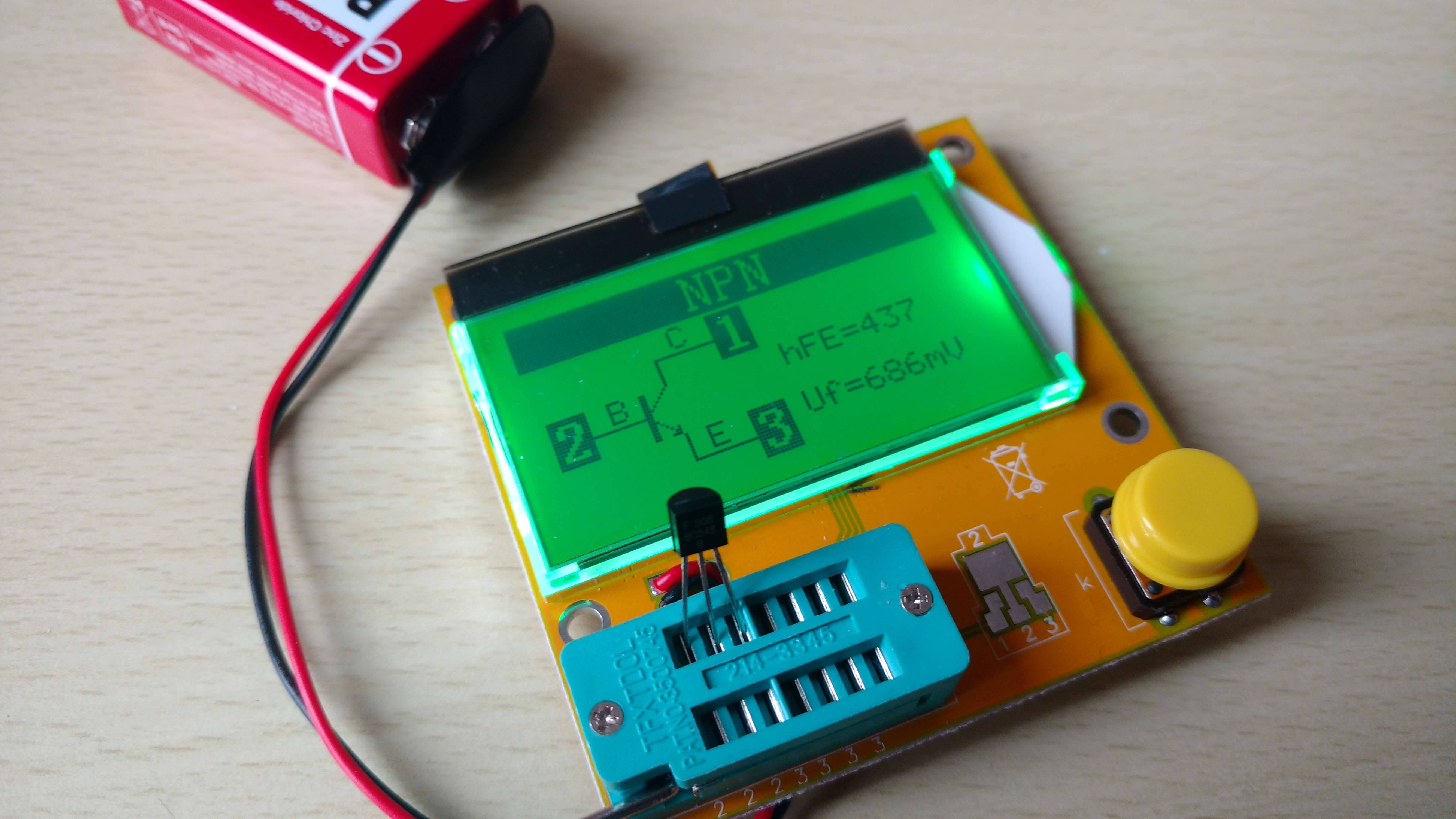
See that the cable is at the top of the LCD on the tester.
I made the necessary modifications for using the library with the T3 transistor tester, for both C and Arduino. I put everything in a repository on github. Now that I had a video library, I could start to work on the game.
Why T-Rex?
First of all, it is an almost monochrome game (the clouds are of a lighter gray), so it would be just fine on the LCD. Second, I would say it is kind of simple. I mean, I don’t know any game programming and got it working(sort of). Also, it is popular and easily recognizable. Finally, dinosaurs are super.
I found a github repository with he t-rex runner game extracted from chromium. From the files there I could get the sprites and have a look at the game code, to see how to reproduce it. Many thanks to Wayou for sharing.
Graphics
I got the following image from the repository mentioned above. Then, I resized it so that the eye of the rex would be one pixel in size.
![]()
Then I had the exciting task of cutting all the dino, ground and cacti sprites. I used gimp for cutting and converting them to bitmap.
![]() Then, I used Adafruit’s repository recommended tool, bmp2glc for converting each of the bitmaps to .h files with byte arrays.
Then, I used Adafruit’s repository recommended tool, bmp2glc for converting each of the bitmaps to .h files with byte arrays.
Game Logic
I believe the game can be summed up in looping through:
- Calculate the new positions of the sprites
- Check collision between cacti and rex
- Draw the sprites to the LCD
- Update score
These steps are ok to work on. But after getting some sprites to the screen, I noticed there were some serious problems with speed. I could not even test at that speed. So we better have a look at that first.
Performance issues
I had two problems I could not fix:
First, the Atmega was running at 8MHz – This is 40% of the maximum clock speed that the mega328p can have. I still wanted it to work as a component tester, so I would not change the crystal.
Second, the display is hooked up to a soft SPI – This means that instead of transferring a byte at just one clock cycle, the micro has to shift some data, test a bit, write to the data and clock GPIOs… all this eight times per byte.
All the other problems were related to the LCD library or the game itself. Without Adafruit’s library I would not even work on this project, it was quite useful and easy to use, but just needed some tweaks for best performance.
I saw some code that could be reworked:
The library uses a buffer, first we write sprites to the buffer and then write the buffer to the LCD.
// the most basic function, set a single pixel
void setpixel(uint8_t *buff, uint8_t x, uint8_t y, uint8_t color) {
  if ((x >= LCDWIDTH) || (y >= LCDHEIGHT))
    return;

  // x is which column
  if (color)
    buff[x+ (y/8)*128] |= _BV(7-(y%8));
  else
    buff[x+ (y/8)*128] &= ~_BV(7-(y%8));
}

void drawbitmap(uint8_t *buff, uint8_t x, uint8_t y,
		const uint8_t bitmap, uint8_t w, uint8_t h,
		uint8_t color) {
  for (uint8_t j=0; j<h; j++) {
    for (uint8_t i=0; i<w; i++ ) {
      if (pgm_read_byte(bitmap + i + (j/8)*w) & _BV(j%8)) {
	setpixel(buff, x+i, y+j, color);
      }
    }
  }
}
So to write a bitmap to the buffer, it is done bit by bit by calling setpixel() every pixel. I modified this to write a byte already:
void drawbitmap2(uint8_t *buff, uint8_t x, uint8_t y,
const uint8_t *bitmap, uint8_t w, uint8_t h,uint8_t color) {
  if((y%8)==0){
    for (uint8_t j=0; j<(h/8); j++) {
      for (uint8_t i=0; i<w; i++ ) {
        if(color){
          buff[(x+i)+((j+(y/8))*128)]|=pgm_read_byte(bitmap + i + (j)*w);
        }else{
          buff[(x+i)+((j+(y/8))*128)]&=~pgm_read_byte(bitmap + i + (j)*w);
        }
      }
    }
  }else{
    uint8_t shift=y%8;
    for (uint8_t j=0; j<(h/8); j++) {
      for (uint8_t i=0; i<w; i++ ) {
        if(color){
          buff[(x+i)+((j+(y/8))*128)]|=(pgm_read_byte(bitmap + i + (j)*w)<<shift);
          buff[(x+i)+((j+1+(y/8))*128)]|=(pgm_read_byte(bitmap + i + (j)*w)>>(8-shift));
        }else{
          buff[(x+i)+((j+(y/8))*128)]&=~(pgm_read_byte(bitmap + i + (j)*w)<<shift);
          buff[(x+i)+((j+1+(y/8))*128)]&=~(pgm_read_byte(bitmap + i + (j)*w)>>(8-shift));
        }
      }
    }
  }
}
If a byte from the bitmap is aligned to a page on the LCD, just copy it, if not, break it into two bytes and write them to the buffer. I got smart here and aligned the sprites in the game, so the only sprite that needs the ‘else’ above is the dino, but only when jumping.
Another problem was that to update the screen, it was necessary to write the whole buffer to the LCD. At first I thought of writing only the pages modified, but then I realised I could create a new function to write only part of the buffer, giving the coordinates to the function.
The write_buffer() funtion:
void write_buffer(uint8_t *buffer) {
  uint8_t c, p;
  for(p = 0; p < 8; p++) {
      st7565_command(CMD_SET_PAGE | p);
      st7565_command(CMD_SET_COLUMN_LOWER | 0);
      st7565_command(CMD_SET_COLUMN_UPPER | 0);
      st7565_command(CMD_RMW);

      for(c = 0; c < 128; c++) {
        st7565_data(buffer[(128*p)+c]);
      }
   }
}
A new function, to write only part of the buffer:
void write_part(uint8_t *buffer,uint8_t x, uint8_t y, uint8_t w,uint8_t h) {
  uint8_t c, p;
  for(p = 0; p < 8; p++) {
    if((p*8)>=y && (p*8)<(y+h)){
      st7565_command(CMD_SET_PAGE | p);

      st7565_command(CMD_SET_COLUMN_LOWER | (y&0x0f));
      st7565_command(CMD_SET_COLUMN_UPPER | ((y>>4)&0x0f));
      st7565_command(CMD_RMW);

      for(c = x; c < x+w; c++) {
        st7565_data(buffer[(128*p)+c]);
      }
    }
  }
}
Then I could manage the LCD updates by just giving the coordinates of the sprites.
Another small thing, the ST7565 does not have a command for clearing the screen. And the library has a function for this, but it just writes 1024 zeros to the screen. Still, I got from one of the example codes that is best just writing the negative of the sprites to same place than clearing the whole screen.
If made right, the positions of the rex should be calculated on real time. But calculating square roots, powers and stuff in a 8 bit micro controller would be a pain and take so long. So the trajectory of the jump is fixed. Instead of calculating the parable, the code just acess a table with the next y value for the dinosaur.
Game Logic (Cont.)
Ok, I said before that the game would be summed up in a loop to:
- Calculate the new positions of the sprites
As it would be really slow to calculate the trajectory of the dino when jumping, by using speed and aceleration parameters. I opted to just using a table with fixed y values. When jumping the rex position is gotten from the following array:
points[]={38,31,28,25,23,22,20,19,18,17,16,15,14,14,13,12,12,11,11,10,10,10,9,9,9,8,8,8,8,8,8};
The cacti and ground, however, are just having their x values decremented every frame.
- Check collision between cacti and the rex
Here, I think the usual is using hitboxes. But in this case, I figured out that by when writing a bitmap to the buffer, I could check if there was at least a pixel, really a single pixel, where the bitmaps colided. It works like this, before I write a byte to the buffer, I and (&) the previous byte with the new byte. Only when a bit is set at the same position in both bytes, we have a collision.
The drawbitmap() function we saw before becomes:
uint8_t drawbitmap2(uint8_t *buff, uint8_t x, uint8_t y,const uint8_t *bitmap, uint8_t w, uint8_t h,uint8_t color) {
  uint8_t new_byte,status=0,prev_byte;
  if((y%8)==0){
    for (uint8_t j=0; j<(h/8); j++) {
      if(y>LCDHEIGHT)break;
      for (uint8_t i=0; i<w; i++ ) {
        if(x+i>=LCDWIDTH)break;
        if(color){
          new_byte=pgm_read_byte(bitmap + i + (j)*w);
          prev_byte=buff[(x+i)+((j+(y/8))*128)];
          status=status|(new_byte&prev_byte);
          buff[(x+i)+((j+(y/8))*128)]=prev_byte|new_byte;
        }else{
          buff[(x+i)+((j+(y/8))*128)]&=~pgm_read_byte(bitmap + i + (j)*w);
        }
      }
    }
  }else{
    uint8_t shift=y%8;
    for (uint8_t j=0; j<(h/8); j++) {
      if(y>LCDHEIGHT)break;
      for (uint8_t i=0; i<w; i++ ) {
        if(x+i>=LCDWIDTH)break;
        if(color){
          new_byte=(pgm_read_byte(bitmap + i + (j)*w)<<shift);
          prev_byte=buff[(x+i)+((j+(y/8))*128)];
          status=status|(new_byte&prev_byte);
          buff[(x+i)+((j+(y/8))*128)]=prev_byte|new_byte;
          //
          if(y>(LCDHEIGHT-8))continue;

          new_byte=(pgm_read_byte(bitmap + i + (j)*w)>>(8-shift));
          prev_byte=buff[(x+i)+((j+1+(y/8))*128)];
          status=status|(new_byte&prev_byte);
          buff[(x+i)+((j+1+(y/8))*128)]=prev_byte|new_byte;
        }else{
          buff[(x+i)+((j+(y/8))*128)]&=~(pgm_read_byte(bitmap + i + (j)*w)<<shift);
          if(y>(LCDHEIGHT-8))continue;
          buff[(x+i)+((j+1+(y/8))*128)]&=~(pgm_read_byte(bitmap + i + (j)*w)>>(8-shift));
        }
      }
    }
  }
  return status;
}
And in the game code I have something like:
draw_dino(Rex,1);
...
bump=draw_cactus(cactus,1);
...
if(bump){
  //game over
}
- Draw the sprites to the LCD
I just use the library functions to write the bitmaps to the LCD. However, because of performance and ghosting reasons, the bitmaps are only written to the LCD when moving position of the object(like the cacti) or changing bitmap (like when the dino changes the leg touching the gorund).
- Update score
I use the EEPROM to keep the hiscore when the the board is turned off. I looked for a place not used by the old firmware, so I could change the flash without worrying about the EEPROM.
//at startup:
score=0;
highscore=get_score();//from eeprom

//when game over:
if(score>highscore)update_score(score);//to eeprom
- More
I used a unconnected ADC pin as a source of randomness for srand(), this means I have to wait for a ADC conversion. I also think there’s some math in srand(and I also use % to top the number returned) that slows things just a bit, but I am just guessing, I haven’t seen the code. I tried just getting a number from the timer in CTC mode. but it is just awful. I need to study some of this when I have time.
I put a lot of time in fixing the code, removing unnecessary stuff, only writing to the LCD when really needed, making the library faster. At first I could not even see the problems, but with time I got more and more aware of ways of not letting the game waste time doing unnecessary tasks.
There is some ghosting characteristic to the display. There is no way to fix this, but I guess it is okay, even the Game Boy had some :)
 The LCD takes some time to change the stage of a pixel, so between frames there is some visible ghosting. It gets better at low fps.
About input, the button present on the board is used to start up the microcontroller. Every time it is pressed, the LCD back-light goes off. I use another button connected to terminals 1 and 3 of the ZIF socket to allow input without turning off the back-light.
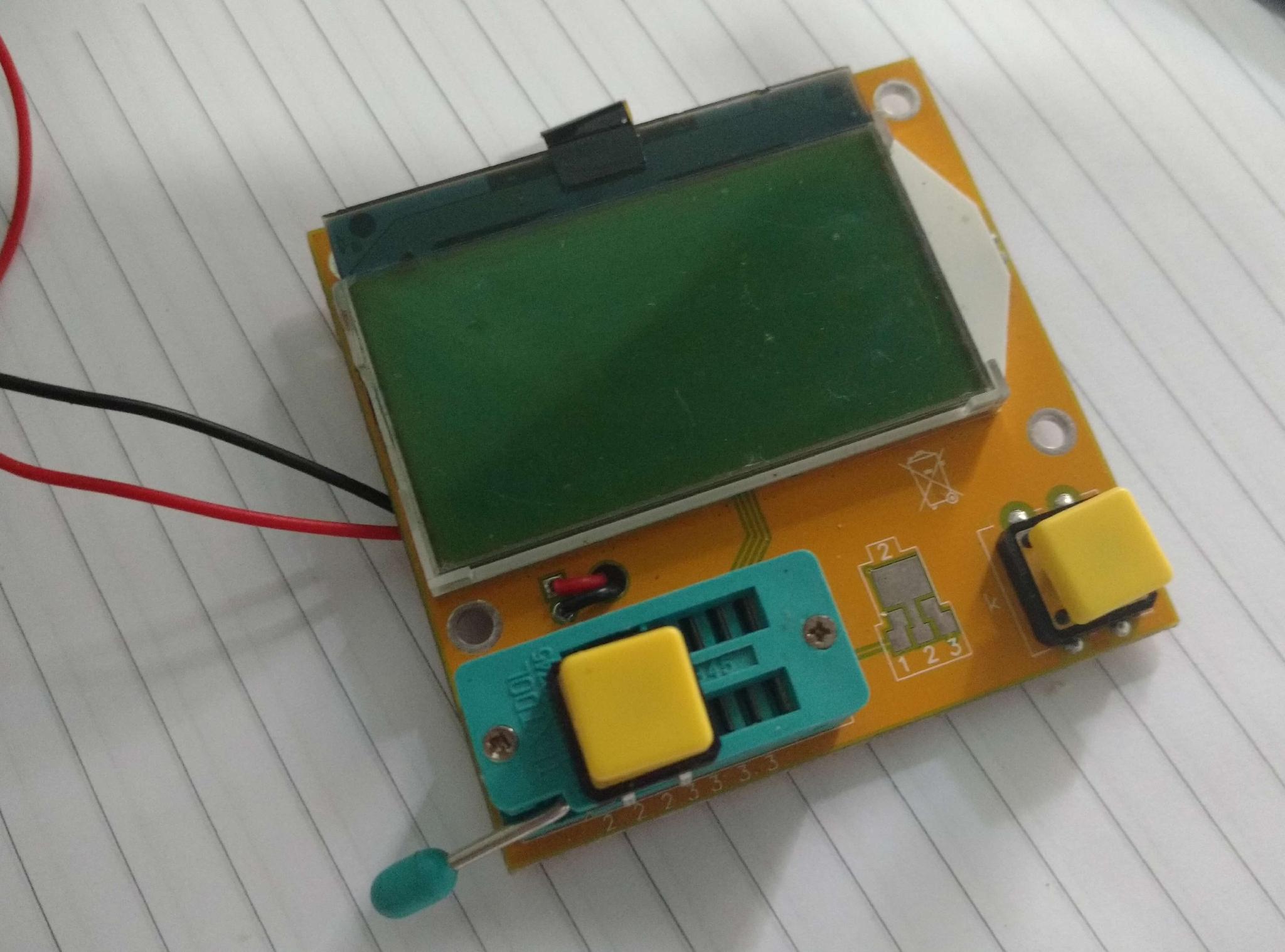 Button connected between 1 and 3 in the ZIF socket
Video
You can see a video of the thing below.
The cacti look better in real life. I guess because of the persistence of vision effect. The component tester would be better for slower games. I guess arkanoid or space invaders would be pretty cool, but the back-light would have to be turned off in order to use both buttons.
Conclusions
I spent more time in this project than I wanted to, so it is not finished yet. It is missing the pterodactyls, for example, and the way cacti repeat in the original game. It is just I am fed up for putting to much time in this, but I will probably work on it in the future with another microcontroller or LCD. The code is available in a github repo here.
This was mostly a way of training C programming, and I am quite satisfied with the results. I got to know how manipulate bitmaps, got more used to pointers, structures and some other small things. Speeding up things was challenging, but quite fun.
I would like to thank Rafael for his interest in the project, we discussed some of the ideas that I implemented here.
Well, I think that is it for now.
Thanks for reading. See ya in a next post o/


4 thoughts to “Getting the T-Rex Endless Runner to work on a Component Tester”