
Welcome! In this post I talk about the reverse engineering of the GM328A transistor tester. I have drawn the schematics of the board and compiled new firmware for it. As a bonus, I also programmed Tetris for it.
Intro
Some time ago I wrote an article where I programmed one T3 LCR meter / transistor tester to run a clone of the cute t-rex game from the chrome browser. That LCR meter was one of the most useful instruments I ever had, specially because I have the same digital multimeter since I was 15 and that does not even measure caps. Unfortunately, the former did not endure the constant abuse (I often used it as a badge when going to conferences and such) and the LCD ribbon broke.

I scoped eBay for a replacement, and the T4 successor seemed a bit off and I did not like it at all. Prices for the T3 had gone up also. Thankfully I found something even better, this version was named GM328A.
![]()
This LCR meter has a color LCD, which is great in case I continue using these as a made up badge. It also packs frequency and voltage measurement, a power jack, and PWM output. Additionally, the one I found was a mere 10 USD.
That said, these LCR meters make great development boards, in this post I detail the process I used to figure out the schematics for this model and also show a version of Tetris I coded for it. The reverse engineer efforts here are mostly related to the printed circuit board and not to the firmware.
Before we proceed, I have to mention that all these transistor testers are based on the same project, originally created by Markus Frejek and continued by Karl-Heinz. You can find information and the code at mikrocontroller.net. Still, there are tons of different variations of the circuit sold on eBay and the like, in this post I reverse engineered the schematics for this board only.
So, to sum up. In this project I:
- Reversed engineered the printed circuit board;
- Fixed a mistake on the frequency measurement circuit;
- Adjusted and compiled the AVR transistor tester code to fit this board;
- Programmed Tetris for it.
Before anything, I thought it was good idea to backup the original firmware, but this is where I hit the first obstacle. Although the board seems hacker-friendly, even having a socket for the microcontroller, its firmware was locked. So instead of copying the firmware to the computer, I replaced the microcontroller. This way I could always have the original firmware and still use the board if I messed up.
GM328A PCB reverse engineering
As expected, the gm328a is also based on the Atmega328 (hence the name, I guess). This is the same microcontroller used in many Arduino boards.
I could have unsoldered everything in order to see the PCB traces clearly, but I did not want to ruin the tester, so I only used the continuity tester function of my multi-meter to figure out where the components were connected.This is a difficult approach, since one component can be connected to many others. Still, the circuit is small enough to not give me a headache.
Good thing that many of the passive components have values printed on the board. I have also used a magnifying glass to see the traces and the markings of the ICs. For some parts, I had to search online for compatible pinouts. The display, for example, I had to find it online (It is the ST7735) to figure out its pinout.
After a lot of testing and online browsing, I came up with the following schematic. You can click the image for full size.

I did the best I could with just the continuity test. It may not be perfect but it it is good enough for its purpose, which is telling where the important bits are connected. you can find these schematics in Eagle format in the project’s repository.
Bonus: Board Fix
While studying the board, I came across something really strange. A via on the board was not connected to anything. By the looks, it seemed that the trace coming from PD4 should be connected to the frequency measurement circuit. Later, I looked at Markus’ firmware and PD4 was indeed the pin used for frequency measurement there.

I tried to test the frequency measurement function to see if was missing something, but it did not work at all. I concluded that it was in fact a mistake on the PCB layout. I fixed the problem by removing the soldermask from the via and bridging it with solder to the closest resistor.

After that, the frequency measurement worked as it should.
New firmware
Differently from the T3, this board does not have a programming port. Although the MCU is socketed and can be removed, that is a pain to do and I often accidentally bend the pins. I decided to add a temporary programming port for directly connecting the board to one of my trusty USBASP programmers.

Anyways, now with the pinout information from the reverse engineering in hands, I was able to compile a new firmware for the board. Firstly I downloaded the 1.34 version of the Transistor tester code from mikrocontroller.net. You can find all versions of the AVR transistor tester firmware here.
Then I just adjusted the pinouts according to the schematic I showed above, selected the type of LCD and configured the available functions and soon enough I had the transistor tester working with the new code. After some tweaking, I compared the results from the new compiled firmware with the one which came with the board. These results were collected after calibration of the board for both firmware versions.

You can find the edited firmware in the github repository. There you can also view the history of the files config.h, config328.h and Makefile to see what I have changed from the main fork.

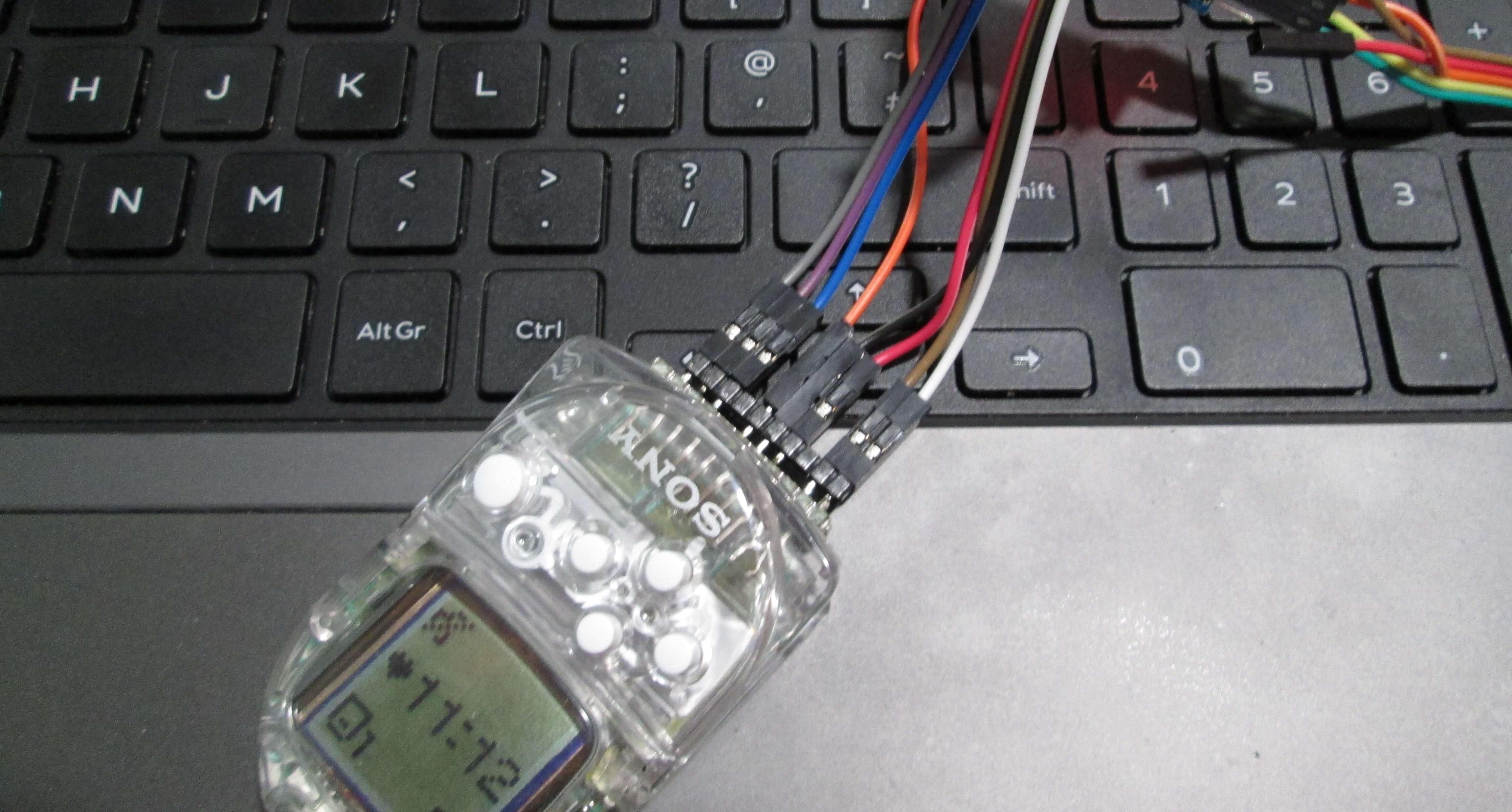
New firmware running on the board (2N3904 transistor)
Tetris
Of course I had to program a game for this one (even though I know almost nothing about programming games). If the code seems like a spaghetti feast, you know why.
This gm328a has an encoder with a built in push button. So this is like having three buttons. This setup was really good for arkanoid or maybe pong, but I chose Tetris for two reasons: First, the levels are the same when progressing, the only thing that changes is the speed the blocks fall and the scoring. Second, Rafael said in the past that it was possible to program a working tetris in a single day, so I was really keen to see how long it would take me. Even using Arduino and libraries, It took me some days.
Last time I had a lot of “fun” programming the t-rex game using just bare C. I decided that this time I would use Arduino. BTW, I translated the whole Arduino reference to Portuguese, so I kind know the functions by heart.
I also used some external libraries, listed below:
- Adafruit’s GFX library
- Adafruit’s ST7735 LCD library
- Matthias Hertel’s Rotary Encoder library
Programming the game was still quite the challenge. For starters, the LCD and the rotary encoder are connected to the same pins, so I had to alternate between writing data to the display or checking the encoder. Besides, I had to write data to the LCD very quicky, and watch the encoder the rest of the time. Otherwise the game would miss the turns of the encoder. The fact that the SPI display was being bit-banged did not help too. Because of this, I opted for using very simple squares for representing the tetrominos, not any wasting time filling them too.
To program the gm328a using Arduino, I just select Arduino Pro or Pro mini on the board menu of the IDE. Then I choose Atmega328 (3.3V, 8Mhz). Notice that I chose 3.3V even if the board is 5V. It is ok, as I don’t use the ADC in this project and there is not an 5V, 8Mhz option. This way I don’t have to edit board files outside the IDE or whatever, I find these kinds of workarounds a pain in the neck. To upload the code I use a USBASP with the option Upload Using Programmer (Ctrl + Shift + U).
I did not get the timing right last time. But now I have studied a little, this led me to implement an interrupt driven loop.
#include "game.h"
#include "sound.h"

void setup(void) {
  gameInit();
}

void loop() {
  gameTick();
  drawBuffer();
  waitInterrupt();
}
The game loop is updated mostly every 60Hz, while the screen is not. Although the display is SPI driven, it is bit-banged with the GPIOs. Also, the MCU runs at 8Mhz, while it could be ran at 20MHz without problems. Thus, updating the screen, which happens only when something has to change on the screen, takes a lot of time compared to computing the game state. The gameTick() function verifies the inputs and calculates the next frame, you can see it below:
void gameTick(void) {
  side = getEncoderPos();
  if (side == S_LEFT)  tet.move(S_LEFT);
  if (side == S_RIGHT) tet.move(S_RIGHT);
  if (buttonWasPressed()) tet.rotate();
  tet.update();
  soundTick();
}
As the encoder is used for input, spinning it moves the piece sideways, while clicking it rotates the tetromino. An optional push button can be connected between pins 1 and 3 of the testing socket to act as a drop button, the button which accelerates the fall of the blocks.
Unfortunately, I have to disable the encoder when not using it. The encoder shares the LCD display pins and is only active inside the waitInterrupt() function. This function, alongside the interrupt service routine of the timer 1 can be seen below:
void waitInterrupt(void) {
  intFlag = 1;
  enableEncoder();
  while (intFlag) {
    encoder.tick();
  }
  disableEncoder();
}

ISR(TIMER1_OVF_vect) { // Timer 1 interrupt service routine (60Hz)
  TCNT1 = 65015;   // preload timer
  intFlag = 0;
}
So, after the game is done calculating everything for the current frame, it waits for the next frame while polling the encoder. It is obvious that when the LCD is being used, some turns of the encoder will be missed, but there is no way of getting around this issue.
Back to the problem of the screen taking too much time to communicate. In order to decrease the update times as much as possible, only the parts of the screen which need to be updated are rewritten to the LCD. For example, let’s see the function that moves a tetromino:
void Tetromino::move(int side) {
    ...
    //part of the code not relevant to this example has been removed,
    //see the complete code on the Github repository
    ...
    //paints the old tetromino position black
    buffer[block[0]] = C_BLACK;
    buffer[block[1]] = C_BLACK;
    buffer[block[2]] = C_BLACK;
    buffer[block[3]] = C_BLACK;
    //ad it to the queue to be drawn
    queueInsert(block[0]);
    queueInsert(block[1]);
    queueInsert(block[2]);
    queueInsert(block[3]);

    block[0] += side; block[1] += side; block[2] += side; block[3] += side;

    // fills the new position and add it to the queue to be drawn
    buffer[block[0]] = color;
    buffer[block[1]] = color;
    buffer[block[2]] = color;
    buffer[block[3]] = color;

    queueInsert(block[0]);
    queueInsert(block[1]);
    queueInsert(block[2]);
    queueInsert(block[3]);

  }
}
A tetromino is composed of four blocks, and these blocks can only be placed at 200 possible positions (the tetris “field” is 10×20 blocks). This 200 positions are kept in the variable “Buffer”, which contains the color of each block. Thus, the old position of a block of the moving tetronimo, which is to be erased, and the new position, which is to be colored, are added to an queue. Every frame the drawing function checks this queue for data and only if there are blocks present, these are drawn on the screen:
//draws only the blocks listed on the queue, called every frame
void drawBuffer(void) {
  while (!queueIsEmpty()) {
    int i = queueRemoveData();
    tft.drawRect(X0 + (i % 10)*BLOCK_SIZE, Y0 + (i / 10)*BLOCK_SIZE, BLOCK_SIZE, BLOCK_SIZE, buffer[i]);
  }
  // if game over, shows gameover screen
  if (gameover) {
    showGameOverScreen();
  }
}
The rest of the screen elements are updated asyncronoulsy. Anyways, when these are updated, the game flow is usually blocked, so it is ok. For example, when a line is cleared, the score is updated, all the blocks above that line have to come down and the player has to wait for the next new tetromino to appear.
I could not finish the game without the iconic korobeiniki, so had to implement sound. For this purpose, I use the PWM output terminal. This was very simple, as I already wrote dozens of song sketches for arduino as a sheet music reading exercise. The tone function from Arduino can generate a square wave in the background, using the timer 2. Then I simply check every frame if its is time to change the note being played or rest between notes.
// notes of the moledy followed by the duration.
// a 4 means a quarter note, 8 an eighteenth , 16 sixteenth, so on
// !!negative numbers are used to represent dotted notes,
// so -4 means a dotted quarter note, that is, a quarter plus an eighteenth!!
int melody[] = {
  //Based on the arrangement at https://www.flutetunes.com/tunes.php?id=192
  NOTE_E5, 4,  NOTE_B4, 8,  NOTE_C5, 8,  NOTE_D5, 4,  NOTE_C5, 8,  NOTE_B4, 8,
  NOTE_A4, 4,  NOTE_A4, 8,  NOTE_C5, 8,  NOTE_E5, 4,  NOTE_D5, 8,  NOTE_C5, 8,
  NOTE_B4, -4,  NOTE_C5, 8,  NOTE_D5, 4,  NOTE_E5, 4,
  NOTE_C5, 4,  NOTE_A4, 4,  NOTE_A4, 8,  NOTE_A4, 4,  NOTE_B4, 8,  NOTE_C5, 8,
  ...
};

// sizeof gives the number of bytes, each int value is composed of two bytes (16 bits)
// there are two values per note (pitch and duration), so for each note there are four bytes
int notes = sizeof(melody) / sizeof(melody[0]) / 2;
// this calculates the duration of a whole note in ms (60s/tempo)*4 beats
int wholenote = (60000 * 4) / tempo;
int divider = 0, noteDuration = 0;

unsigned int index = 0;
unsigned long next=0;

void soundTick(void) {
  if (millis() > next) {
    if (index < notes * 2) {
      // stop the waveform generation before the next note.
      noTone(buzzer);

      // calculates the duration of the note
      divider = melody[index + 1];

      if (divider > 0) {
        // regular note, just proceed
        noteDuration = (wholenote) / divider;
      } else if (divider < 0) {
        // dotted notes are represented with negative durations!!
        noteDuration = (wholenote) / abs(divider);
        noteDuration *= 1.5; // increases the duration in half for dotted notes
      }
      next = millis() + noteDuration;

      // we only play the note for 90% of the duration, leaving 10% as a pause
      tone(buzzer, melody[index], noteDuration * 0.9);
      index += 2;
    } else {
      index = 0;
      next = millis();
    }
  }
}
I won’t discuss the whole code, otherwise this post would become even longer. You can see the complete code on Github. Don’t expect it to be good, but is is well commented! Below I leave a short video of he game running:
There are still a few bugs that rarely appear and are annoying to debug. I won’t lose sleep over this though, as this game was just a proof of concept and not the main objective of the project.
That is it for now. Thanks for reading until here.
See you next time o/
Relacionado / Related Posts
 Engenharia Reversa do Testador de Componentes GM328A + Tetris!
 Game Boy Pak Reader & The Cartridge Header.
- Rodando o jogo do T-Rex em um testador de componentes
 Backup e gravação de Memory Card PS1 (Arduino & Python)
 SNES controller to PC adapter with Arduino micro.
 Fazendo placas de circuito em uma CNC Arduino
I would love to try this, but the G328A i bought wont stay powered on. As soon as you release encoder, itpowers down. Of course china doesnt want to help lol, so i may have to buy another and pray that one works, so i can try this :) Plus have a working tester lol..
I have the new version and I am totally disappointed, it is unpredictable. Resistance is ok but Capacitor way out. When switch on it goes to setup mode the cursor does not move, and immediately it goes into testing mode and keeps on blinking “Vext=0mv” , and after about few minutes it shows some imaginary capacitor with factastic values, then it switches off. I do not know what does it means.
Oh, that is awful.
There is a hex file in the repository that you can program to a spare Atmega and see if that works better.
It’s missing the (.eep) file. The (.hex)file alone will not work . How can I get it?
By the way, iam using USBASP with AVRDUDESS 2.2
the fuses as this L=0xf7 H=0xd9 E=0xfc bit clock 1.5MHZ ATmega328p
Got mentioned GM328A from Banggood with stock firmware version v1.12k. Frequency meter works, but it is way off (52.8 Hz on screen for 50 Hz input). Seems circuit design for frequency metering here is not good at all. Other things seems working. Square wave signal generator is Ok. Encoder reaction in menu is slow, though it may be software problem. Build quality is, erm… so so. Board wasn’t washed after assembling and had dried liquid flux residues with huge fingerprints all over board. Had to clean them off. Polycarbonate casing top plate near ZIF socket broke in middle during assembling. Maybe I will make different case for it later.
Any ideas how to fix frequency meter? And how to change firmware – do I need to purchase another Atmega chip or is possible to reflash existing one?
Hi, thanks for your comment.
The stock firmware in mine was awful was well.
My board had a problem on the frequency measurement circuit, as explained in the text.
Yes, you can reflash the existing Atmega, but you will lose the original firmware and I can not guarantee my version is better. You need an AVR programmer though, these go really cheap on ebay. You probably may also use an Arduino if you already have one.
Robson
Hello
I have a GM328 TFT LCD Chinese KIT, which uses a red pcb with DIP components.
https://id.aliexpress.com/item/32645287865.html
then the HT7550 regulator got burned, so the firmware was broken. I tried to use the hex & eep GM328A file from
https://www.mikrocontroller.net/svnbrowser/transistortester/Software/trunk/mega328_color_kit/.
My GM328 test works fine, but the test menu is different from before.
My GM328 used to have a menu
– IR RC Detector / Decoder
– IR RC Transmitter
– Temperature Sensor DS18B20
– DHT11
now the menu does not exist. where I can download hex & eep files that have a test menu like the one above.
thank you
You probably will have to compile a custom program with the options you want in the config.h file.
For example, in mine there is:
//#define HW_IR_RECEIVER
So the IR receiver is not available. You have to be aware of the MCU pins used however.
Hi there,
I was wondering if anyone can help me!
I have a few “LCR-T4 ATmega328 Digital Transistor Tester” with faulty displays ( connector on display board problem).
Is there any way to find a replacement for the dsiplay board?
Many thanks,
Zamfir
I also have a broken LCR meter with the same problem and could not find a replacement LCD. That is why bought the GM328A, not worries of the ribbon breaking as the LCD is tightly secured.
Hi Robson,
I tried the Tetris: it is very good.
In Github is ComponentTester.hex (version 1.34) but the file for the EEPROM is missing, could you upload it?
Thank you
Sorry for the late reply.
There was no eeprom file, I just did a simple calibration shorting the three contacts.
I can record the hex file on the TL866II Plus recorder: and how do I do this, because I tried and ended up losing the original tester firmware :-(
I don’t have a TL866II, so I don’t know how to use one.
If you figure it out, you could try to program the compiled firmware (hex file) in my repository.
Thank You very much for schematics. Bought one, tested about 20 transistors. After that tester will not switch on anymore. With schematics was able to find broken capacitor and repair tester. It seems electrolytic capacitor on 7550 input pin is 10V or less, because died from unregulated 9V wall adapter, that gives out ~12V when unloaded.
Hi Sigunas, I’m glad the schematics helped you!
Robson, which compiler used to compile the code and generate the hexadecimal, because I recorded with the tl866II plus, it didn’t work, I recorded as described in the blog, and it even works, but it gives crazy characters on the LCD. What could I have done wrong? thankful
I used avr-gcc and avr-libc on linux with the makefile provided in the original repository.
I guess that is probably not very easy to do if you use windows. You can always create a virtual machine though.
Also, is your gm328a the exact same version as this post?
The original version was 1.12, I tried to record 1.34 and others, both on the TL866 and as described in the post, but all of them, the lcs appear strange characters, sometimes it works right and suddenly everything is messed up.
And yes, the circuit is the same as described in the post. As I was unable to update, I ended up buying another one, but I want to see if I can recover this one, but the whole secret is in the ATMEGA 328p fuses
Robson asked a question, what linux did you use for recording with the avr? What if you have a specific fuse to change or which ones to use, and if you can read with the same circuit, or just program?
Hi Francisco, sorry for the late reply.
I have used Ubuntu linux.
The fuse bits were programmed by the Makefile, I suppose.
I will check them out and reply here.
I could not read the original firmware as it was locked, but I could read the one I compiled used the same programmer I used to write the firmware.
The fuse bit values are lfuse = 0xf7, hfuse = d9, efuse = 0xfc
Thank you I will try again. Thank you for your attention.
You’re welcome. Hope it did work!
i bought a GM328A russian language version by mistake. Doh! I need english. Is there a way to reflash with english?
thanks
There is a hex file in my repository. You can try try that one, but no guarantee it will work, some people had trouble. I recommend you flash another atmega328 and swap the microcontrollers. You may also have to program the microcontroller fuse bits, please read the comments above.
where can i study flash atmega328pu online?. i have a malfunctioning Gm328a lcr. I have tried to copy from another Gm328 lcr which still works or straight from the new version of firmware. but it doesn’t work correctly. i am currently using win7. Does the OS have to be linux? Can you help me?
Thank you for your attention.
Hi, I had to change the display on one of these and its now got an offset, I have found you can change the display offset in the config.h file, but I don’t know how to change and recompile everything. My display has a green tab which denotes how much of an offset? Any chance you can advise?
I can upload new .hex and .eep firmware to the device, but I havn’t got a clue about how to compile everthing?
Thanks, Jas