Intro
Some time ago, I was browsing some Internet when I believe I got and ad to a CNC milling machine from gearbest. It was 30% off and at time (140$, plus 40$ for shipping to Brazil) and it did seem to be a very good deal. I ended up buying it, but why would I even need one in first place?
I have electronics as a hobby and probably as a trade in the future. I am a electrical engineering student, but never found electric power systems appealing. Thus, I spend more energy on programming, circuit design, analog electronics etcetera etcetera.
Nevertheless, I never had any reliable way of prototyping projects. Usually, as can be seem in many posts here, I frequently used veroboard to try out circuits. There are many problems to that:
- Too much soldering, and consequently, fumes;
- Can get very messy when using too many wires;
- Mainly through hole components.
All right, but I could use a laser printer and transfer method, but:
- I don’t have access to a laser printer, haven’t ever thought of buying one, as they are super expensive here;
- Nasty chemicals. A pleasure to use, clean and dispose;
- Need to drill holes anyway.
This is why a milling machine seemed a good option, I knew it had its drawbacks though:
- Dirt. The pcb materials can be very dangerous to inhale.
- Designing and milling a board can be time consuming, not very fast prototyping
I bought the machine as an impulse. When it arrived in Brazil, I was taxed 60% in customs. Still, I did not have the chance to regret it, as still seemed a fair deal. I could not find cnc machines as this one here, even from scalpers.
When I had the machine arrive at my door, it was not the model I bought originally, but seemed better quality (good for me).
I received the machine in January, but only now I could finish this write up. First, because it took me some time to get to know how to use it efficiently. Secondly because of college.
Just a quick note here:
I know that anyone can get cheap PCBs from china nowadays. But I live in Brazil, and just to receive this machine, it took me 70 days of waiting. I got some gifts from the Arduino team and they arrived in 128 days. Sometimes things take 6 months to arrive and these days I have seen people receiving stuff they bought in the last black friday in November. I won’t expect months for prototipe PCBs, so there is that.
Briefing
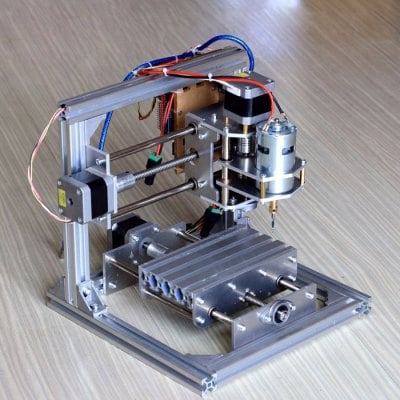
This CNC is sold as an engraving machine. Its frame is made of aluminum, so it is quite sturdy. Some people had luck using it for pcbs, and I can confirm it works fine. It is a bit small though.
- Work area: around 10*13cm, if you can get to hold the board all right, its own table is a little smaller than this.
- Technically, the package has everything you need (apart from computer software), even the power supplies. Yes, two of them. I changed some parts though.
- It uses GRBL 0.9 running on the cheapest arduino UNO board, also included.Already configured in my case.
- GRBL and the arduino shield have support to autolevel
- The spindle motor speed can’t be controlled. It is either on or off.
Assembling
C’mon, there are many tutorials for assembling it online. I don’t have a good camera anyway, so we will be skipping this. I will leave some links at the end of the article though.
Ah, there are not manuals or anything, just the parts. That’s what cheap gets you. Anyways, it is like pro lego, just put the parts together.

Fixes
The product page states:
“Modification and customization of the 3D printer is strictly forbidden. We will take no responsibility for any problems resulting from modifications.”
Funny. Go ahead.
All right, I think I assembled the machine as the manufacturers intended, but I did “some” tweaking to make it better
First, the most problematic, the Z axis:
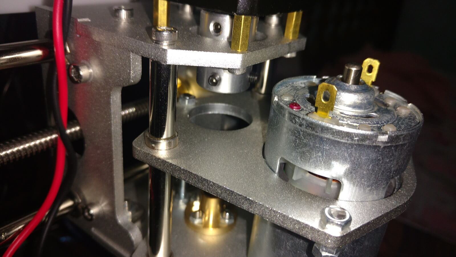
- There were some standoffs included in the package for holding the pieces where the milling motor is mounted. They were thinner than the holes they were supposed to be fit into. This led to a lot of misalignment. I substituted then for screws with nuts, as can be seen below. I used a piece of metal to make sure the two parallel parts were perfectly aligned, just fit it between the two close to the screws and adjusted the nuts accordingly.
- There was a significant amount of play in the Z axis, this was due to some imperfection in the bushings on the said axis. I fortunately had some bushings from inkjet printers I disassembled before, so I replaced the originals with them. It worked fine.

The working area:
- The CNC table is tiny. It is actually smaller than the axis can go. I added a piece of scrap wood above the aluminum table, holding it with the original screws. I recommend you to use wood, as it can be drilled into without major problems if something goes wrong. Also, it isolates the PCB from the metal structure when auto-leveling.
Added auto-level:
- GRBL has support to auto-level, but the machine does not use it by default. I simply added jumper cables to pin A5 and GND and used alligator clip cables to extend them. It is important to make sure the positive lead is connected to the board and the negative one to the bit. The other way around the machine will mistakenly register false contacts.
Stepper config:
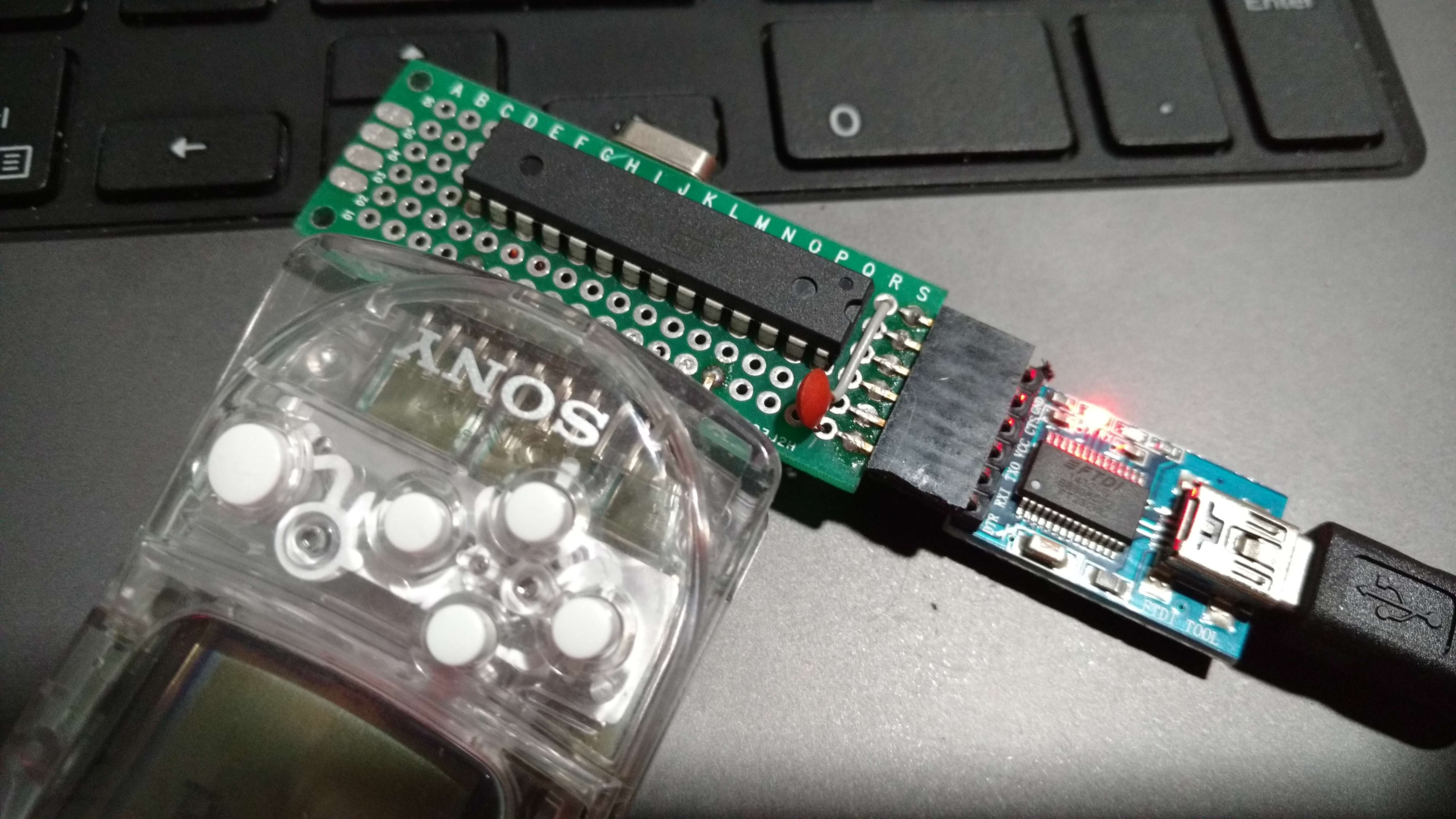
All my stepper motors look exactly the same, but one of them had a different label from the the other two. Thankfully I noticed this before assembling the machine. Thus, I used the different motor in the Z axis. Later, I noticed this motor was only moving half of what it was told to move, so I had to double the current number of steps per millimeter. This is quite easy, first open up the Arduino IDE and select the serial terminal (You can use other terminal too, help yourself).
Type $$ to see the current GRBL settings, mine were as follows:
$0=10 (step pulse, usec)
$1=25 (step idle delay, msec)
$2=0 (step port invert mask:00000000)
$3=3 (dir port invert mask:00000011)
$4=0 (step enable invert, bool)
$5=0 (limit pins invert, bool)
$6=0 (probe pin invert, bool)
$10=3 (status report mask:00000011)
$11=0.010 (junction deviation, mm)
$12=0.002 (arc tolerance, mm)
$13=0 (report inches, bool)
$20=0 (soft limits, bool)
$21=0 (hard limits, bool)
$22=0 (homing cycle, bool)
$23=0 (homing dir invert mask:00000000)
$24=25.000 (homing feed, mm/min)
$25=500.000 (homing seek, mm/min)
$26=250 (homing debounce, msec)
$27=1.000 (homing pull-off, mm)
$100=800.000 (x, step/mm)
$101=800.000 (y, step/mm)
$102=800.000 (z, step/mm)
$110=400.000 (x max rate, mm/min)
$111=400.000 (y max rate, mm/min)
$112=400.000 (z max rate, mm/min)
$120=200.000 (x accel, mm/sec^2)
$121=200.000 (y accel, mm/sec^2)
$122=200.000 (z accel, mm/sec^2)
$130=200.000 (x max travel, mm)
$131=200.000 (y max travel, mm)
$132=200.000 (z max travel, mm)
So I had to double the value of the 102 variable to compensate for the different motor, this was done simply typing “$102=1600.000” in the terminal. I received a “ok” as response. Typing $$ again, returned the following:
$0=10 (step pulse, usec)
$1=25 (step idle delay, msec)
$2=0 (step port invert mask:00000000)
$3=3 (dir port invert mask:00000011)
$4=0 (step enable invert, bool)
$5=0 (limit pins invert, bool)
$6=0 (probe pin invert, bool)
$10=3 (status report mask:00000011)
$11=0.010 (junction deviation, mm)
$12=0.002 (arc tolerance, mm)
$13=0 (report inches, bool)
$20=0 (soft limits, bool)
$21=0 (hard limits, bool)
$22=0 (homing cycle, bool)
$23=0 (homing dir invert mask:00000000)
$24=25.000 (homing feed, mm/min)
$25=500.000 (homing seek, mm/min)
$26=250 (homing debounce, msec)
$27=1.000 (homing pull-off, mm)
$100=800.000 (x, step/mm)
$101=800.000 (y, step/mm)
$102=1600.000 (z, step/mm)
$110=400.000 (x max rate, mm/min)
$111=400.000 (y max rate, mm/min)
$112=400.000 (z max rate, mm/min)
$120=200.000 (x accel, mm/sec^2)
$121=200.000 (y accel, mm/sec^2)
$122=200.000 (z accel, mm/sec^2)
$130=200.000 (x max travel, mm)
$131=200.000 (y max travel, mm)
$132=200.000 (z max travel, mm)
After this, I could move the Z axis for the correct length showed in bCNC.
Arduino and GRBL
Later I also replaced the Arduino with a better one and updated GRBL to 1.1, I had problems with the machine skipping steps, but I think it may have been the shield was not completely connected.
Next, I will use a design of mine as an example, a sort of tutorial. I will create the gerber files from eagle and then export the correspondent gcode to use with bCNC and explain all the steps.
Eagle and Flatcam
I use GNU/Linux, but I believe the software mentioned here is available for others systems, such as ridiculously expensive and just awful. Next, I will explain how to get a ready eagle board file for milling.
I have been using Eagle, mainly because it is easy, has good component libraries available online (see the adafruit and sparkfun ones), as is free for small boards. I run version 7 though, it is the last one before autodesk bought it and screwed it up. I plan to move to KiCad when I have time to study it, though.


After I create a board using the board layout tools, I export the gerber files (File > CAM Processor).
I will be milling the bottom of a board, so the mirror option will be used. If the top layer is used, this option is not necessary, of course.
To export the milling file, select the layers Bottom (or top), Pads and Vias. Also select GERBER_RX274X as device and hit Process Job to generate the file.

To export the drilling (or excellon) file, select the layers Drills and Holes and then select EXCELLON_24 as device:

Now the milling options will be configured with flatcam.
Flatcam
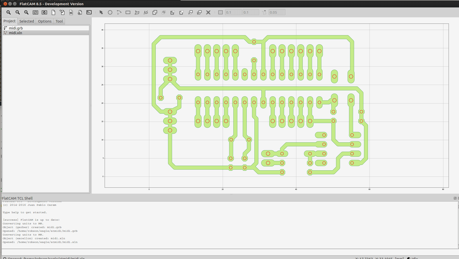
Flatcam is used to configure the gcode files. First, we need to open both the gerber and excellon files.

I prefer to put the board as close as possible to the origin. This is helpful when milling a copper clad slightly bigger than your design, but not obligatory. For this, the offset option is used. In this case, I just moved the design -10 units to the bottom, in both files.

Now both files are close to the the origin:
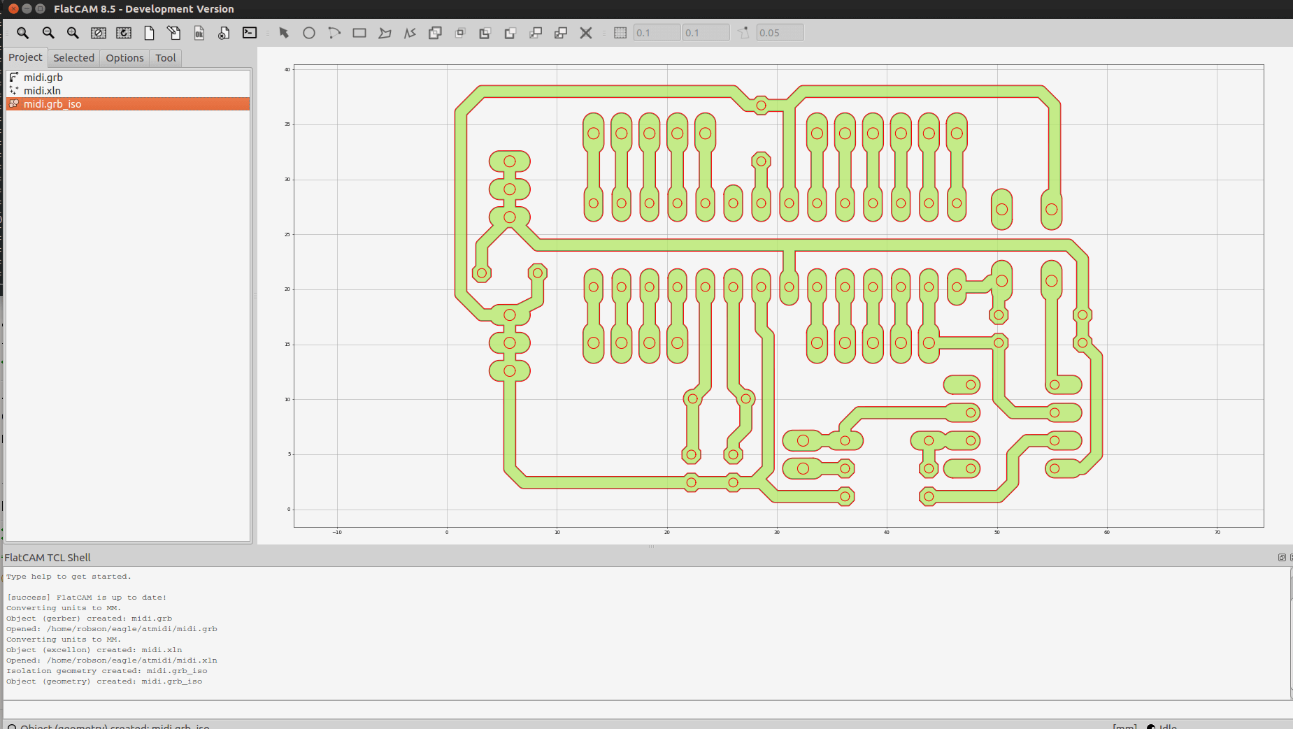
Now, to the the milling file. Double click the gerber file and the tab Selected will show. Here I use a 0.1mm bit, with a single pass. You will see it worked fine, but it is recommended to increase the number of passes, otherwise you will probably have shorts when soldering.

After clinking generate geometry, a file with the same name, but finished in iso, will be created:
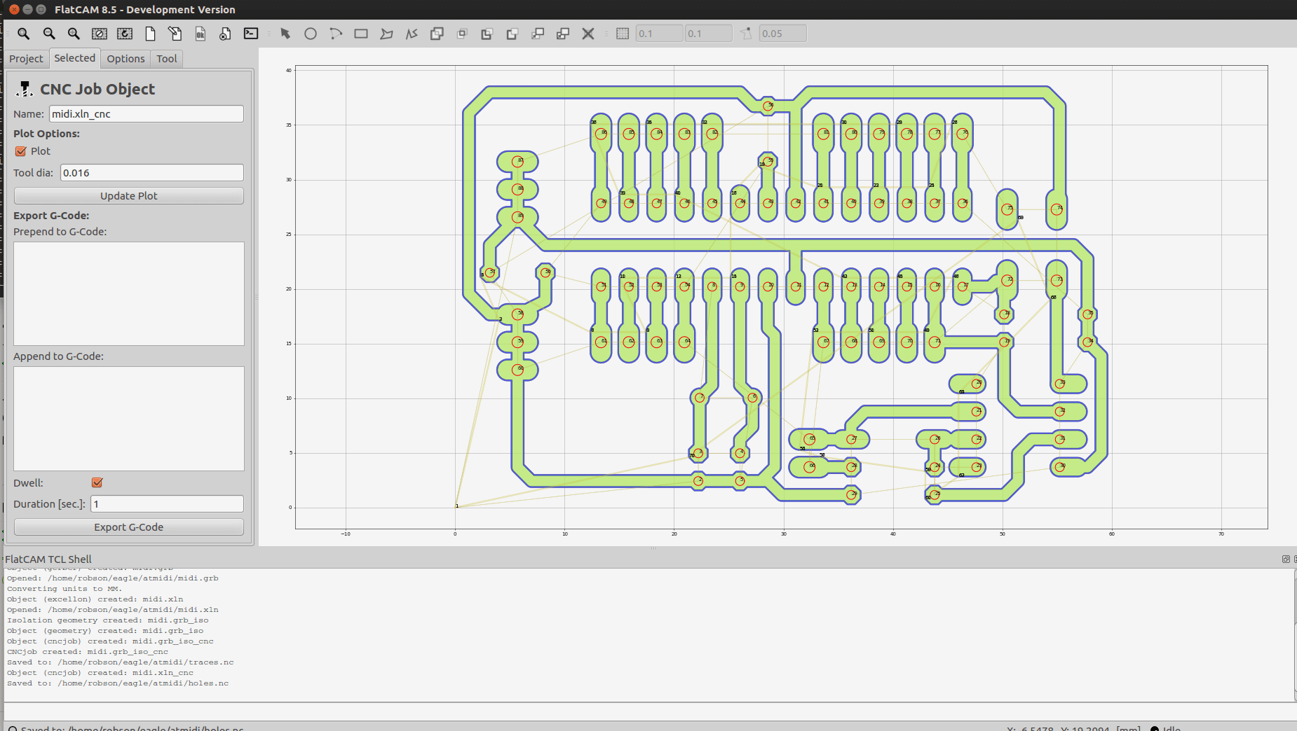
In this file, you will set up the other milling options. I use -0.1mm as cut depth; the tool will raise 5mm above the board when traveling; the feed rate I use 150 mm/s and again the bit diameter is also 0.1mm. I used 3000 rpm as spindle speed, but the machine does not have variable spindle speed, of course. This was necessary though, as the kit was configured to variable speed and expecting a speed value, otherwise the spindle won’t turn on.
You can recompile GRBL and update the arduino to use fixed spindle speed. Its is not trivial, so I will not be discussing it here, maybe in another post.

After clicking generate, we will have the cnc file.

Select the cnc file and export the gcode with a .nc extension.

Next, we have to configure the excellon file, click it to open the Selected tab.

In this file I only had two hole sizes. I should be all right using only a 1mm drill bit. So I selected both, If you have different hole sizes, you might have to create separate files for the correspondent drill bits.
I used 1.6mm as drilling depth, the thickness of the copper clad. 5mm traveling height and a slow feed rate of 75mm/s. You can’t increase the speed too much, or your drill bit might break. Click in generate to create the cnc file.

Click the cnc file and export it. I used the name holes.nc
Similarly, you can create a board cutout. Generate the geometry from the gerber file:

I don’t have a proper bit for cutting, so I use a regular engraving v bit to just score the board, so I can just snap it. The cutting depth used was 0.8mm, with a feed rate of 75mm/s.

Milling with bCNC
First I hold the board with a thick double sided tape. Be generous, otherwise the board may come loose and you will probably have to start again with a clean board. Ah, don’t forget to use a board that fits your design.

bCNC is used to mill and drill the board using the gcode files created with flatcam. First, open the serial port the cnc is connected to.
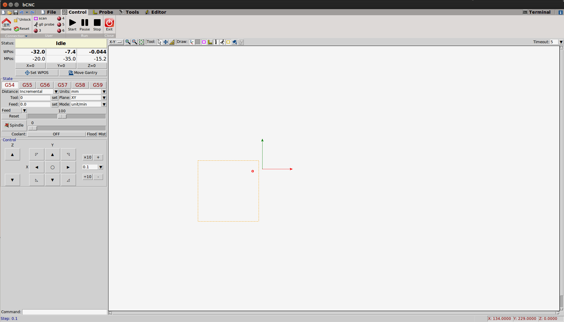
Move the tool to the bottom left corner of your copper board. The z axis must be barely be touching the board surface.

When finished, zero the three axes by clicking X=0, Y=0 and Z=0:

Next, open the nc file you want to mill.

Now it is time for auto-level. It defines the quality of the board, if done correctly, will guarantee a perfect routing. I made sure to get it working as soon as I assembled the machine. A CNC without auto-level may leave some parts of a board without milling, or go too deep when it should not. Usually copper clads have imperfections, or are visibly bent. The Autolevel routine measures the board surface height, taking these measurements into account when milling the board.

Click the Probe tab, then Autolevel. Click the margin button to select the scanning area. You can adjust the number of points by selecting N in the Autolevel panel at the left-hand side.
Also, it is very important to select the Z limits. I used a -2.0mm min value, so in case the probe does not find the board, the procedure will stop 2mm below zero, avoiding further damage.

When finished setting up the values, make sure your probes are connected correctly and hit scan.
When the auto leveling finishes, the working area will have been mapped as the figure bellow. This is the cutout file, but the calibration is the same. I forgot to take a snapshot with the other file.

Everything is read, the file can now be milled, but don’t forget to remove the auto level probe! I forgot once and the spindle rotated the probe cable making a mess.
To start the milling, just hit the play button in the Control tab.
Finished the routing file, you can open the drilling file, keep the auto level measurements when asked. As the drilling generally is taller than the v cutting bit, the Z axis must be zeroed again:
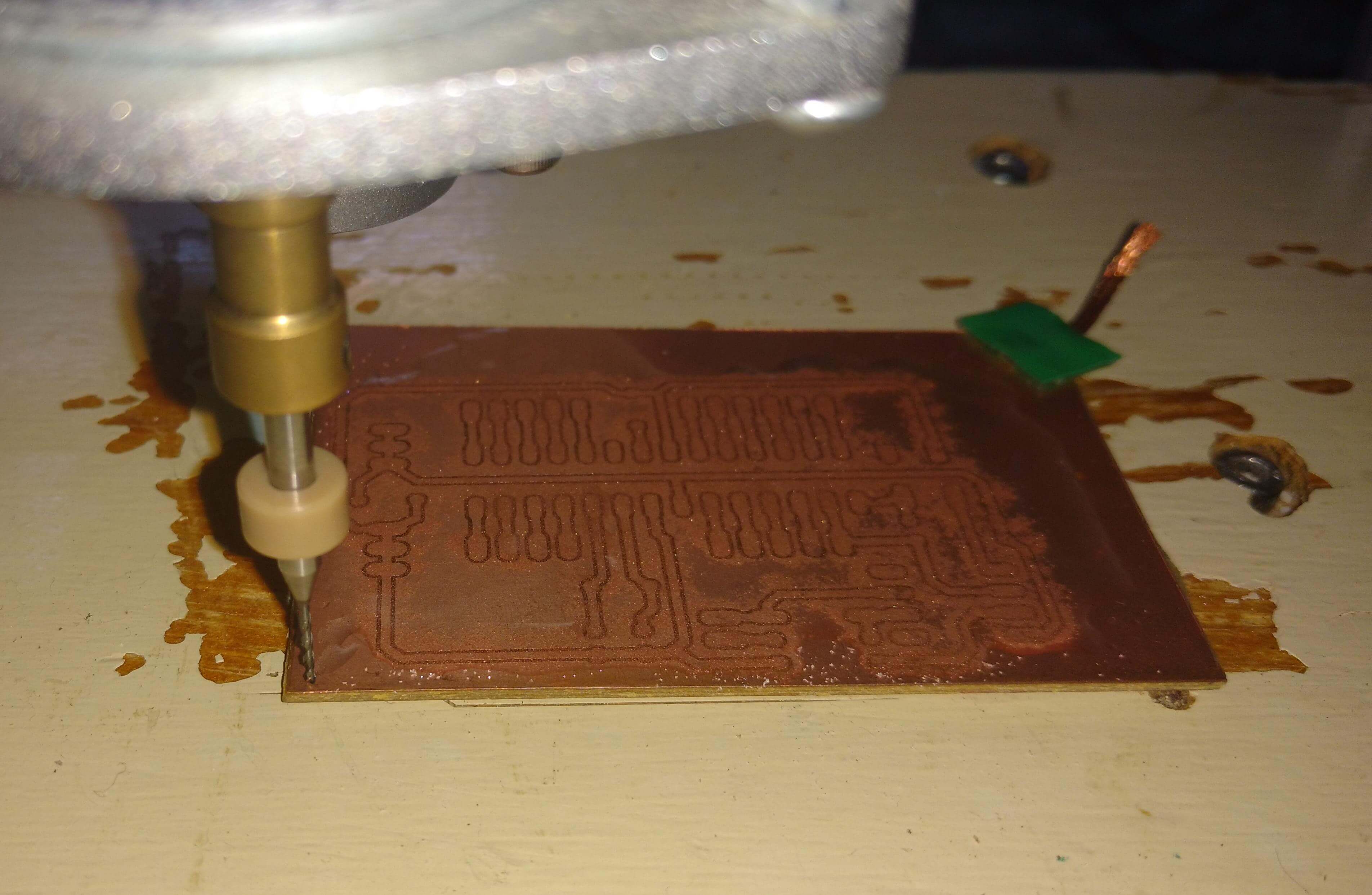
Next picture shows the drilling process on bCNC.

Lastly, the cutout file is opened. The Z axis must be zeroed again.
If everything went ok, I should have a nice PCB now.
Final result
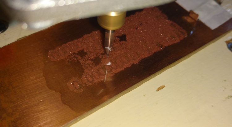
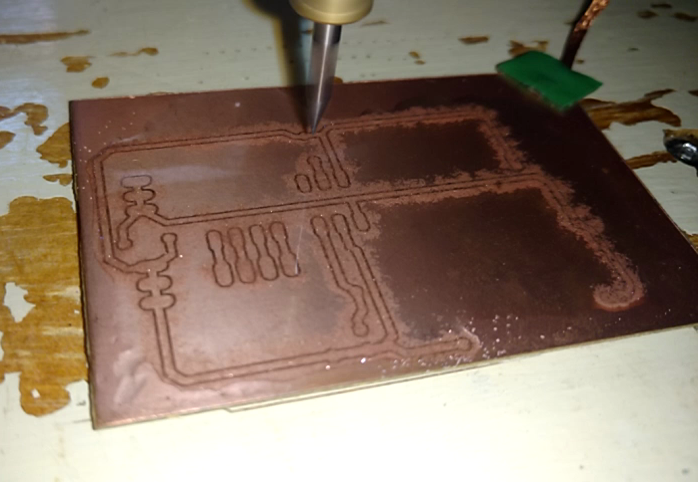
The board was milled without problems, as it can be seen below:

I just regret not increasing the pads. The board works perfectly anyway, I just had to be careful when soldering.
The finished board:
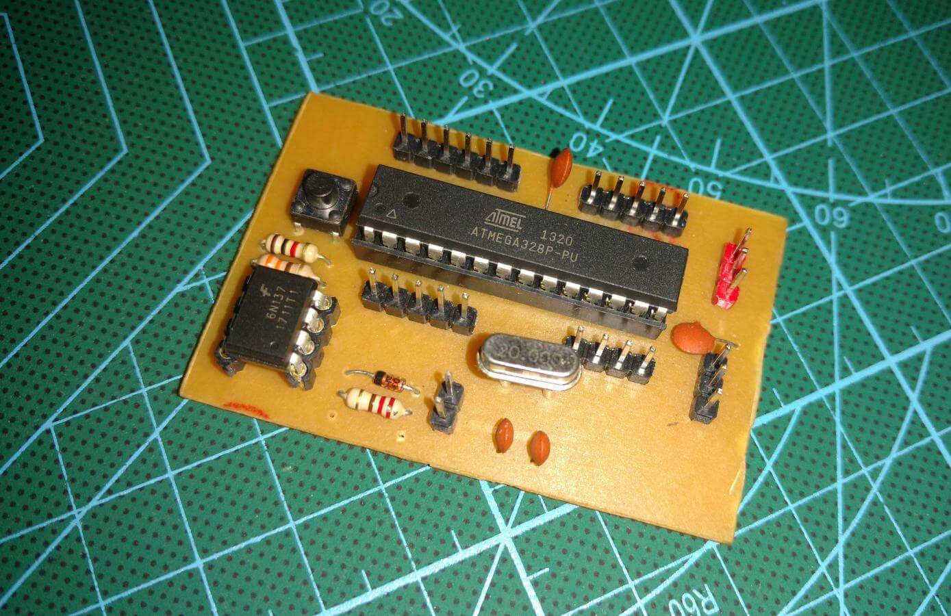
I created it to experiment with MIDI.
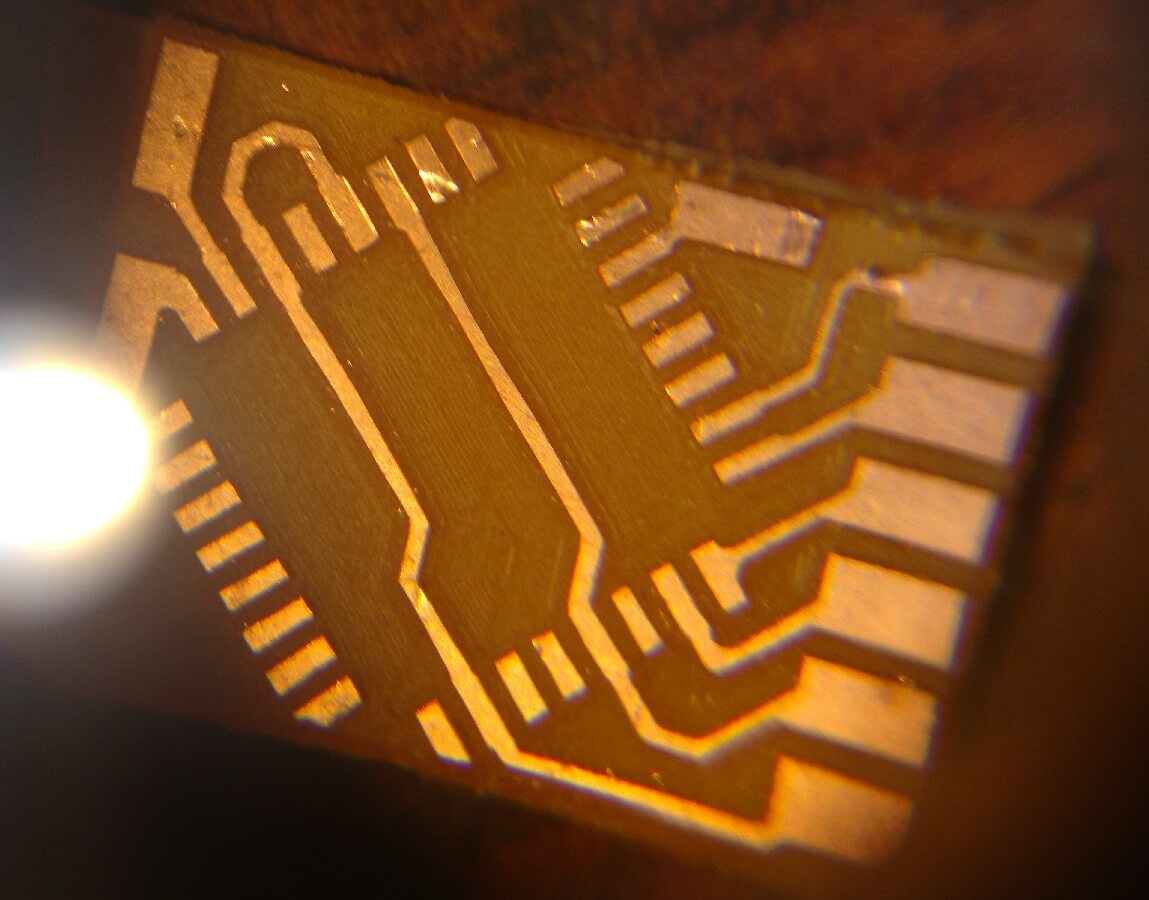
Can the CNC mill smd boards, though?
The video below has parts of the leveling, milling, and drilling processes. It can be seen that I pour machine oil over the board, the oil suspends the bakelite particles, stopping them from escaping to the air.
Conclusions
I am quite happy with the machine now, as now I have a way of making better prototypes. It took me some time to learn how to use it and to fix some issues, but now it is working better than I expected.
The construction of the machine is quite sturdy, and replacement parts are available if necessary. It uses an arduino board, which is super easy to update.
Having excellent quality software that works on Linux is a huge plus. But the software is also available to the other operational systems parodies.
Now, I only have to know how to make double sided PCBs :)
That’s it for now. Thanks for reading!
References:
T8 CNC product page – Gearbest
The cheaper model – Gearbest
T8 CNC Assembly – Sreenzone
Another T8 CNC Assembly – HomoFaciens
Eagle how to – Flatcam
Conecting GRBL – GRBL Wiki


Excellent article! I’ve used many of the software that you mentioned, but instead of Eagle I used KiCAD. I did something similar for another cnc milling machine. Could you please explain how did you installed/compiled FlatCAM under linux. I used it but on Windows 7.
Hi Felipe ,sorry for the late reply, was not notified of your comment.
Very simple, the latest release can be downloade from https://bitbucket.org/jpcgt/flatcam/downloads/
Then I used setup_ubuntu.sh with:
$ sudo sh setup_ubuntu.sh
I guess this works with every debian based distribution, but I use Ubuntu anyways. If I am not wrong, this only installs dependencies, as flatcam can be run from the folder you downloaded with:
$python FlatCAM.py
I set up a shortcut with the command and stick it to the ubuntu sidebar for openning with a click when needed.
I had the same question. For my CNC PCB drilling experience, I used PCGtoGCode converter plug-in from Eagle. It works, but is tedious.
Hi Mike ,sorry for the late reply, was not notified of your comment as well.
As explained in the comment above:
Very simple, the latest release can be downloade from https://bitbucket.org/jpcgt/flatcam/downloads/
Then I used setup_ubuntu.sh with:
$ sudo sh setup_ubuntu.sh
I guess this works with every debian based distribution, but I use Ubuntu anyways. If I am not wrong, this just installs dependencies, as flatcam can be run from the folder you downloaded with:
$python FlatCAM.py
I set up a shortcut with the command and stick it to the ubuntu sidebar for openning with a click when needed.
Hi,
Firtsly, congrats for this awesome post.
I was thinking about buying a solution like this to make PCBs at home. Its not my job, only a hobby.
What is the diference between
T8 CNC product page – Gearbest
The cheaper model – Gearbest
??
When I change the plug for EU plug, its seems the same machine.
Thanks in advance.
Hi Soler
I guess the difference is just in the parts used. For example, the cheaper model uses rigid couplings instead of flexible ones. Also, some parts are made of plastic instead of brass. An amazing assembly guide of the cheaper CNC with a ton of pictures can be seen here: https://www.instructables.com/id/Mini-CNC-Engraver/
Hi, I gave up with my T8 CNC pcb milling project due to terrible runout on the stock spindle. Frustrating as it is 99% there! Any ideas or upgrades. Was thinking of using a drone motor like the Ant Mill. Cheers.
Hi Brad. Sorry, I have not upgraded mine, so I don’t have any recommendations. I could not find the “Ant Mill”, only the natural phenomenon where ants walk to death in a circle. The Other mill from Bantam Tools uses a brushless motor. I suppose one could also adapt something similar to the T8, but that would probably need custom 3D printed parts.
The Ant: https://www.youtube.com/channel/UCX44z-SSL7LzcB4xxgUdHHA/videos
That’s decent finish I guess.
Could you give me a recommendation of bit that you use, feedrate, and best track width that could be achieved?
Many thanks.
Hey nice tutorial it really help me!
just passing to say thanks!
I am glad it helped!