Versão em Português aqui.
Intro
Recently I acquired a SNES. But it only came with a bootleg Mortal Kombat cartridge. Searching for games I found a lot of repro cartridges (Cartridges with the ROM swapped) being sold at local second hand selling websites. The problem is that they are sold usually at prices comparing to those of original untouched cartridges. People should not overprice something they are stealing anyway.
So what? I made this post to prove anyone with an Arduino Mega and some spare components can burn a EPROM for cheap.
How are repro cartridges made ?(usually)
- Find a boring game cartridge (sports specially);
- Burn a EPROM with the desired ROM file;
- Swap the cartridge ROM with the programmed ROM.
Okay, but then why is not everyone making their own repros? Because a programmer is not so cheap. EPROM programmers can be pricey. Even the Chinese ones (It actually depends on the place, here you can pay overpriced from some scumbag or try to import and probably be taxed).
Everything has a cost-benefit ratio and Makers/Hackers are always creating super useful tools with cheap materials. In 2014, I fixed Mega Drive cartridge using a BIOS chips found in scrap. Write flash memory is not trivial, there is a certain algorithm, but still is a relatively simple process. Maybe write EPROM was not complicated.
The Programmer
An EPROM also is a memory. And it’s actually even easier to program than flash memories. To write a byte in EPROM simply select the address via pins A0, A1, A2 … and so on; put the byte to be written in Q0 pins, Q1, Q2 … etc, and give a pulse with a high voltage (13V) in the Vpp pin. The problem is just to do this for 8 * 1024 * 1024 = 8388608 addresses. More information can be found on the 27C801 eprom datasheet.
I’ve used Arduino to program other kinds of memory. Why not also try EPROMs? Also, Arduinos are super cheap (Ebay/Ali express). However, I did not buy an Arduino only to program memories, I have some here at home I use to all kinds of things.
Below is a schematic I came up with for the programmer:
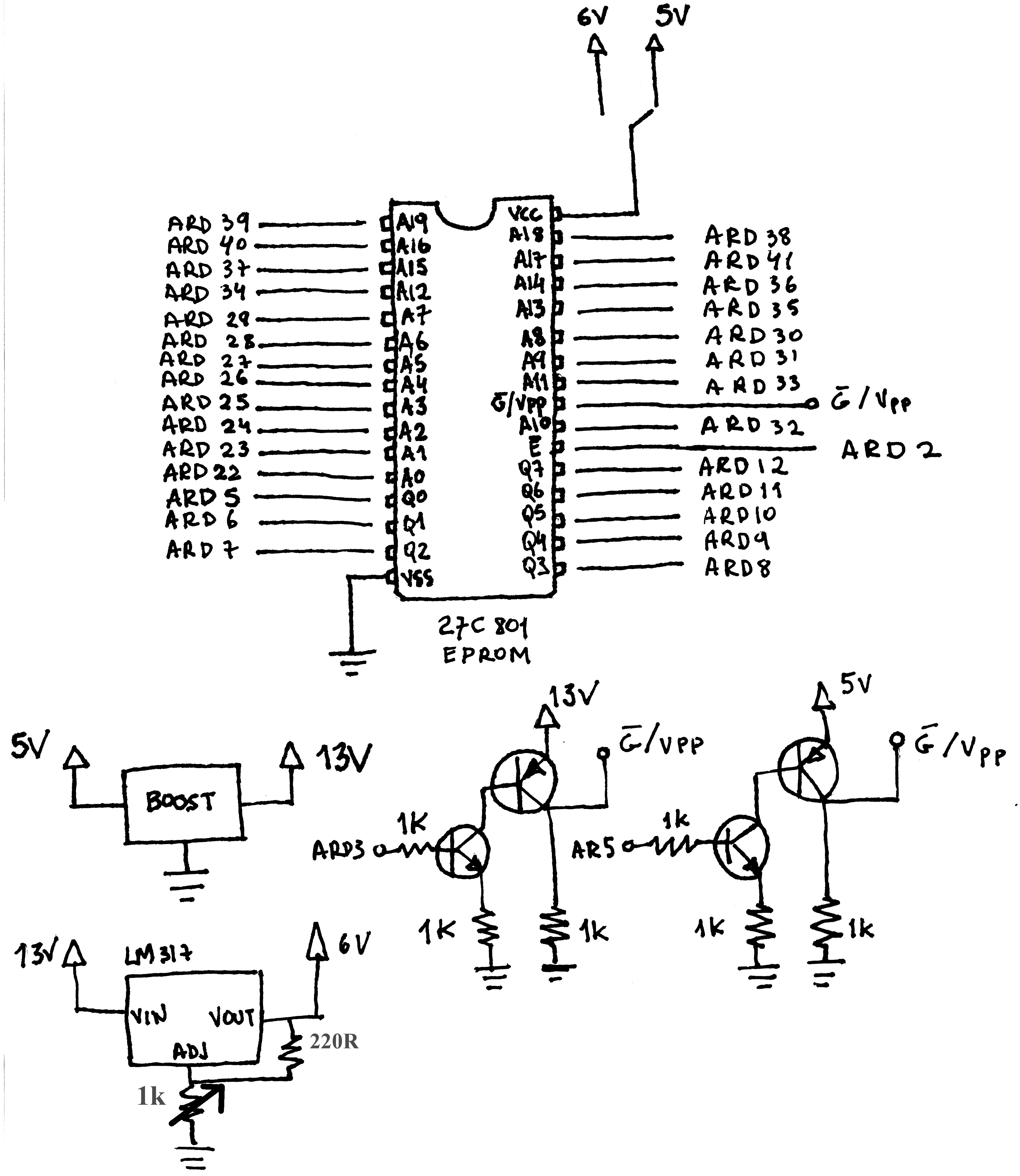 Schematic for the EPROM burner with Arduino.
Also, it should be noted the Eprom needs to be fed 6V when being programmed. Hence the switch in the schematic above. I used a simple jumper and manually change Vcc when needed.
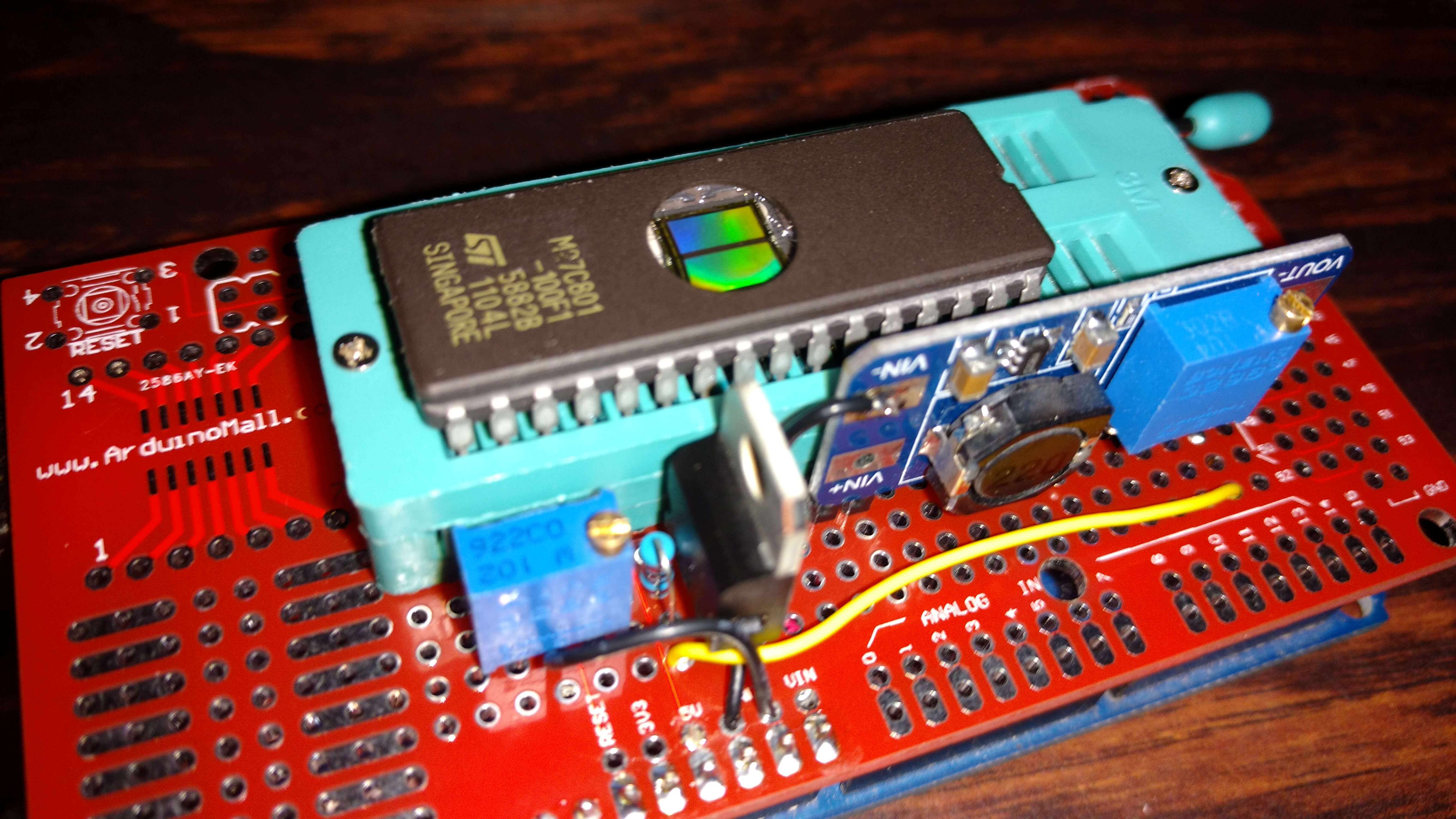
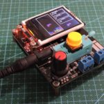
I soldered the circuit on a prototyping shield with a ZIF socket. This makes it eadsy to attach and remove the Eprom. The 13 volts are provided by a boost module, but possibly a 12 volt supply can be used (I did not test, may be you can;). I used a boost so everything is powered by USB.
 EPROM burner shield (Incomplete, still lacked the transistors)
Cool, but in this case, hardware without software is nothing. Python for the win. A Python script reads the data from a file and sends over serial to the Arduino Mega, which receives the data and writes in memory, all very simple.
$ python3 eprom.py
===========================================
           What do you want do do?

              1-dump
              2-burn
              3-info
                              2016
                                  Robson C
===========================================
The project files are available in my github.
The memories I have here I bought on Ebay, about $ 2 each.
Now you know that you can program EPROMS with just a Arduino Mega and some additional components ;). Below are some pictures of the project.
Pics
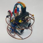
 Cartridge with a Eprom programed.
 Shield finished. I adapted the code to write flash memories as well. But it still has some problems. The code is also in my github anyway.
 Zelda running on the cartridge above.
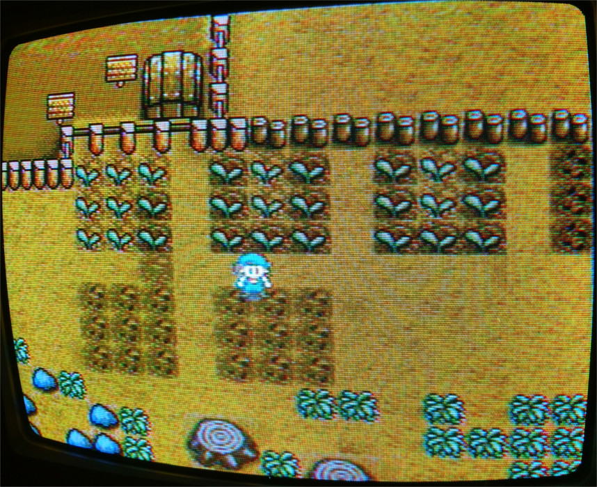
Harvest Moon.

The EPROM eraser I use
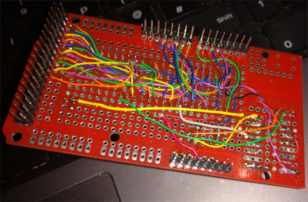
The other side of the board.
Final points
- Please do not use this work for commercial stuff
- Dragão sem Chama does not share ROMS
- Have fun!
See you o/

This work is licensed under a Creative Commons Attribution-NonCommercial 3.0 Unported License.


Da hora. Estou tentando trazer a vida alguns MSX antigos e por alguma razão cosmica dois deles estão com as Eproms muito estranhas (um está respondendo 00h eternamente). Tentei usar um gravador de Eprom de epoca mas o conector serial antigo não tem mais computador que suporte (e se tem nao tem software e bla-bla-bla). Novos programadores sao uma otima opcao, mas pagar 300 dinheiros para provavelmente usar duas vezes nao me anima…
Vou tentar sua ideia de usar o Arduino para elas, vamos ver no que dá !
Opa. Boa sorte! Se o problema for a eprom então é de boa. Se precisar de ajuda deixa um comentário aqui :)
What is the jumper for to switch betweev 5V and 6V? Why not just leave it on 6V?
I actually did leave it working at 6V many times and the eproms are fine. I guess the datasheet says they can work up to 7V, so it should not be a problem.
Hello, is a great proyect that you have between hands. I’m very interested on it, because i have the same trouble, overpriced game carts, low budget and a growing interest on electronics and arduino proyects. It will be awesome if you can share some schematics and component list. Because the model/values of the transistors that you used (except for lm317) are not shown on the post. It will be really appreciated if you do in an update. Thanks in advance :)
Best wishes, Miguel
P.D: I think in the linear regulator with lm317 a 1uf ceramic capacitor is missing, but not sure because you take that 6 volts from the buck boost, right. So the peaks are already atenuated by the regulator if i understand the circuit…
Hi Miguel, thanks!
Sorry, I totally forgot to mention that. The NPN trasnsitors are BC548 and the PNP ones are BC558. I guess they are very easy to find and vey cheap too. I got the boost module (I thisnk is not a buck boost,not sure) from ebay. Yes, also it may miss some capacitors, I just was working much on the code and forgot hardware a bit haha.
Please tell if you can get everything working(or not)!
Hi Robson !
It’s an interesting post ! I’m a web developer, and I want to go back to my fundamentals ^^
I’m a noob in this stuff, and I want to learn with these kind of project, can you help me ?
I’m actually reading some books to learn micro prog and soldering. Have you some advise for me challenge.
I really want to realize this project, it’s a personnal challenge ????
Have an email or any way to chat with you ?
Thx !
Hi Miguel !
It’s an interesting post ! I’m a web developer, and I want to go back to my fundamentals ^^
I’m a noob in this stuff, and I want to learn with these kind of project, can you help me ?
I’m actually reading some books to learn micro prog and soldering. Have you some advise for me challenge.
I really want to realize this project, it’s a personnal challenge ????
Have an email or any way to chat with you ? Mine : geoffrey.trambolho@gmail.com
Thx !
Hi Geoffrey.
I really recomend you to get an Arduino board.
I started in the world of microcontrollers with a Arduino UNO.
There is a huge community and a lot of content about Arduino, so it is easy to understand everything.
Also, Arduinos(UNO, Mega, Micro, Leonardo and so on) generally have a USB port and don’t need a programmer, that is really usefull. You can programm them with a simple click of a button.
From that you may want to dig more and learn assembly, AVR C or ARM stuff, it is up to you.
Good luck!
Hello, i’m elektrobrain from Czech Republic and i’ve like your project, i making advanced version of your programmer, with c# interface and some new features, like recieve chip and pin config from interface to programmer and universal ZIF Socket for any memory (Willem inspirated dil switches :D)
In my current working version i can read and programm 42pin, 32, pin and 28pin memorys only by changing chip in interface.
If you are interest, i can send you my version.
Hi.
I would like to read program from Eprom 27c2000 and you have already developed this programer if you can share it to me on my email address.
regards
princefraz@hotmail.com
Hi Alois … I also like Robson’s project and want to build it as well … your post caught my eye because of the 28/32/40 pin versions … did you publish this at all? … are you willing to share via email? … thank you … dirk.j.martens@gmail.com
Hello, it’s been a while since I wrote the previous comment… Until the date I have the Arduino mega, the prototyping board, the boost converter, the linear converter, the transistors, the ZIF 42pin connector, but not the correct eeproms for writing. Maybe in a month I will have all the materials and then hopefully everything working. Cheers, Miguel :)
Hi Miguel. Sorry for the late reply.
Dont~t worry. Feel free to ask anything about the project here when you have everything.
Robson
Hi, I just came across this post, very cool stuff!
I have a SST39SF040 flash memory, its connections are different from M27C801 and SST39SF020A.
Should I change the schematic or just write another pinout definitions in the arduino sketch in order to get it to work?
Another questions, SST39SF040 and SST39SF020A both have a WE#(Write Enable) pin, I don’t know how to deal with it. Does it have the same mechanism with the VPP pin in M27C801? I haven’t started to study your adruino code, maybe your answer will same much time for me, thanks!
Max.
Hello Max.
Have you had a look at the other repository?
https://github.com/robsoncouto/flash
I wrote a 4Mbit or 512KB memory at the time with that code. I believe your chip should have the same pinout. Don’t use the code for burning eproms, it is not going to work, flash memories use a different algorithm for programming.
Also, for flash you don’t need a 13V power supply, which is awesome.
If you don’t get it working, just ask here.
Robson.
Thanks. I will look into it and will let you know when I make progress.
Besides, Have you imported your schematic into a design app like EAGLE?Would be great if you can share it.
Regards.
Max.
Hello Max.
Unfortunately, I only have the hand-drawn pic you see above.
I even thought about it, but then I would have to make the ZIF socket component and create pinouts and zzzzzzzzzzz hahaha.
Robson.
opa, tudo bem? serviria apenas para super nintendo? queria usar também para outras plataformas, como cps2. teria como? e onde comprar as eproms e qual utiliza-las? enfim, sou iniciante.
Olá João.
Uma vez que você entende o conceito é fácil adaptar pra outras eproms.
Você tem experiencia com CPS2? Essas são aquelas máquinas arcade com street fighter, isso?
Você sabe qual o tamanho médio dos jogos(ROMS)? Também, imagino que sejam 16 bit, correto?
Não entendo sobre essas maquinas, são dificeis até de se encontrar hoje em dia haha.
Robson
Hi there,
I’m very interested in building this programmer but there isnt enough details on the hardware side on how to wire it up. Can you provide some pictures or diagrams for wiring up the transistors to the vpp and the bottom picture of the board? Thanks!
Hello Ben.
The links are fixed now. Sorry about that.
There is a catch in the “schematic”. I cant remember what was it now, but I guess pin five should be pin 4( Arduino). Not sure tough, please check in the code hehe.
Any question, just write them here.
I was also wondering about wiring the dc converter to which pin, as well as the voltage regulator to whatever pin on the chip to the arduino board. This may be much to ask i think. XD
Hi Ben
Connect the dc-dc converter to 5V and adjust it to 13V.
Then from these 13V, you input to the lm317, so it can be dropped down to 6V.
The 13V are connected to the chip only through the transistors. But I chose to connect 6V to the chip manually, to put it in “programming mode”. This voltage is used to program bytes in the addres given to the chip.
If you don’t understand this, please have a look ate the memory datasheet, it is going to clarify things a little.
Wasn’t it about adding a .1uf cap to the lm317 regulator
Nah. It worked fine without it.
But you can add one, sure.
Hey Robson, awesome project and just what I needed for my C64 cartridge I’m trying to build.
I’m using a Teensy 2.0, which doesn’t have enough pins to set the address directly so I’m going thru three 595 shifters instead. I’ve edited your setAddress function accordingly and reading the rom works fine. But when trying to write the python script always craps out here:
while ser.inWaiting() == 0:
time.sleep(0.01)
timeout = timeout-1
if timeout == 0:
print(“could not get a response, please start again\n”)
break
It’s waiting for the writeSector function to send back CHK. Any clue why this would fail or how to start troubleshooting it?
Hi Sven, thanks!
Nice! We gonna work it out
It seems to teensy is not returning the checksum. If I recall correctly, the file is sent to the microcontroller in “sectors”, then the microcontroller sums all the bytes and returns the checksum to the computer, that proceeds to the next bunch if the value is the same as calculated by the computer. This way it is possible to check if there was a problem when writing
Can you see if the teensy is returning anything at all, even if wrong values?
Robson
Thanks for getting back to me so quick. Turns out it really is an issue with the Teensy, just don’t see why. But I’ve hooked up an Arduino UNO instead and it programmed the chip without an issue. I could just leave it at that and be done with it, but really want to figure out why the Teensy can’t handle your code. I thought it might be that it can’t hold the 128 Bytes you’re sending, but looking at the specs of the Teensy 2.0 they’re just about the same as the UNO.
Well, I’ll keep you posted if I find out anything more. But let me know if you have any ideas, too.
Sven
Reading up more on the Teensy, I’m quite certain the issue lies in the difference of the USB to serial buffering:
https://www.pjrc.com/teensy/td_serial.html#txbuffer
Not sure how to adjust your code to account for that, though…
Hi sven, I don’t have a teensy, so I can’t really test this behaviour.
I will have a look at this text you sent me when I free to see if I can come up with any fix.
Did you get the cartridge working when you used the UNO? Would like to read more about this.
Robson
Hello again Sven
Have you tried using the send_now() function mentioned there? Apparently, the teensy accumulates data to make good use of a usb packet (that can be many bytes).
Or you can try to perhaps increase the timeout in the python code.
Robson
Hi again Robson
Yes, I did get the cartridge working fine using the UNO. As for the Teensy, I’ve added the send_now() right after sending the checksum back and increased the timeout and the delay in the python script, but it still fails right on the first 128 bytes. I’m thinking there’s a problem in the receiving side already then. Will need to study the examples they have on the Teensy website for dealing with the receive buffer.
Sven
Hi Sven
Intriguing, I thought that wold work.
I cant help you much, as I can’t replicate the problem.
Anyway, I am glad you got the cartridge working. I guess you are trying to make it work with the teensy as a matter of pride hahaha. Good luck!
Please tell me if you get it working o/
Haha, correct! No need to keep breaking my head over it since I’ve burned all my EPROMS with the UNO, but it still bugs me that I can’t figure out how to get the Teensy to work. Oh well…
can you plz send me to me email a schamatics ready to print for the i didn’t get a lot for the schematics but i am interested in printing one
(edited)
Hello Nabeel
Sorry, everything I have is in the post.
Robson
I will try it on a test board and snd you the photo if some thing want wrong I wish you will help me
sorry but I get this error
>>>
= RESTART: C:\Users\PINBALL\Desktop\eprom-master (15)\eprom-master\eprom.py =
Traceback (most recent call last):
File “C:\Users\PINBALL\Desktop\eprom-master (15)\eprom-master\eprom.py”, line 5, in
ser = Serial.Serial(‘/dev/ttyACM0’, 250000, timeout = 0)
NameError: name ‘Serial’ is not defined
>>>
I do not have much idea of programming but I want to recover some PCV and this programmer loved it.
Hello Javier
It seems you don’t have Pyserial installed. Please install the suitable Pyserial version your Python installation.
Robson
Hello to all. I managed to build the programer, install all the programs and run the burning proces. There is only one problem, the burning is taking right now 14h and stil not finished (about 76%) and it od slowing down. Is this normal?
Hello Jakub. That is very unusual. It takes me some minutes to burn a 1MB eprom.
Do you get any messages when running the code? I believe your setup must be dropping bytes, please try to lower the baud rate and seeing if that makes it more reliable.
Robson
Hello,
I tried different baud rates, down to 9600 and it stopped to read/write anything (just 0% til infinity, it only responds on 250000).
I start to think that the curent draw on 5V is to large when steping up to 13V and that messes up the MEGA procesor.
I prepared the programer to take the 12V from external power suply and 5V USB maby that will help.
The programer was writing data with no errors or messages except: example “Writing data. Current procentage: 90.42%”. Now it broke down with mesage about mising an expected haracter after runing for 28h.
OK, I managed to make it work with baud rate of 9600 (forgot to change it in the *.ino file). It is faster but still 1,5h for 40% of 1MB of data is very long.
Hi Jakub
Did you try stepping it up then?
Trying to get the highest rate? 9600 really is very slow.
Nicely done! I imagine, you can adapt a SD-Card shield in between, to temporarily store the data, making the whole system self-contained. I’ve seen a similar idea, still using the MEGA, and adapted it a little as a ‘sipper’ (reader only), from anything as low as a 2708 to as big as a a a 16MB X8 EEPROM, using just the higher digital outputs (22-29 as data, 30-53 as address) I’d love scanning over your code, and see where I can make improvements on the design as a burner!
Thank you Stephen! Yes, totally possible, but then a lcd or some sort of interface would be needed for selecting the binary file to be burned, right?
The code is available on github, there is a link in the text above. Feel free to fork and adapt as you wish. If you do anything with it, I would be glad to hear!
Robson
Ei, uma pergunta xD
Esse script suporta as EEPROMs 29f, que também são usadas em repros?
29f032, 29f033, 29f016?
Oi Jairo
Essas memórias são do tipo flash e podem ser suportadas pelo meu outro projeto https://github.com/robsoncouto/flash
No entanto podem ser necessárias algumas modificações no tamanho da memória e no número de pinos de endereçamento.
.
Ok. vou dar uma olhada! tô pensando em usar o nano com 2 shift registers, como neste setup:
https://raw.githubusercontent.com/beneater/eeprom-programmer/master/schematic.png
Daora Jairo.
Mas se liga que pra 29f032 por exemplo, acho que você vai precisar de três registradores de deslocamento, já que a memória possui 22 pinos de endereçamento.
oi robson as eeproms que eu tenho (W27C512-45Z) só tem 16 adress pins ao invés de 19 como estão no código, quais são as alterações que eu preciso fazer?
Olá, Godoy.
Já faz muito tempo que não uso esse código e não lembro muito bem.
Procuro no código as variáveis que limitam os for() e ajuste os pinos do arduino também.
Não esqueça de ajustar o tamanho da memória no código python também.
obrigado robson, vou dar uma olhada
robson, eu percebi que não precisa alterar o código, é só não endereçar os valores até o A16, se eu fizer um código que não assume mais do que 512kb o programador não vai ter nenhum conflito, ele só vai ficar enviando um sinal low nos pinos A17 para A19, a não ser que eu tente enviar mais dados do que o eeprom tem capacidade
e se vc utilizar uma eeprom com mais do que 19 adress pins é só enviar um sinal active low dependendo do modelo, mas você não seria capaz de endereçar mais do que 8mbit
Little bit confused with the diagram, AR5 to the 5v NPN-PNP driver doesn’t seem to be referenced in the INO file? It that A5 or D5?, because D5 is in use as a dataPin?
No, this refers to one of the free pins for Arduino 2560 (or compatible) board.
Pin 4 controls the +6V driver (actually I advice to use 6.25V better.) when programming.
Pin 5 controls the +5V driver. But ACTUALLY, if you’re trying to program e.g. a 27C512 take care also to set programBit = LOW and also readBit = LOW when reading, if not you’ll end up reading just zeroes.
In the original design it has readBit=HIGH for reading, doesn’t need that for 27C512 and some other EPROM models.
If you need further help please reply here and I’ll try to help you, I succesfully modified and used this design for 27C512s (very popular eproms).
Hello.
Nice project and very useful info, thanks (muito obrigado haha).
I have to append some detail, I tested a design based on this. In the case of e.g. 27C512 EPROM chips, you don’t need the part of PNP+NPN which deals with the 5V. to EPROM Vcc, just the part which provides the 6V (actually better to set it to about 6.25V when circuit on). This is because this 27C512 configuration for READ has to be readPin=LOW and programPin=LOW, that is, BOTH must be low (see 27C512 datasheet and reading cronogram for details.)
I had a few nightmare-like attempts until I noticed that. I changed that detail, and from then on programming my (2) 27C512s was a breeze.
Thanks again, fica com Deus!
Moises from Spain
Sorry, in the above comment I mixed up the bits hehe. It’s pin GPP that has to remain LOW for READING, not HIGH as in the example EPROM model (I used 27C512s instead.)
Of course you still NEED the Vcc +5V driver and the 6.25V part too… :) my fault.
Just take into account that both program and read control pins must be held LOW for 27C512 reading (and maybe for other models, just take care to browse the corresponding datasheet/s.)
Regards.
To clarify finally (sorry for the mixup):
To program the chip pin VPP (GP) in EPROM 27C512 must be 13V. (most correct is about 12.75 V, see datasheet.)
To read the chip VPP (GP) in EPROM 27C512 must be GND, NOT +5V.
Also I have a Fritzing schema for my final programmer design based on this, will share if anyone out there needs it or can benefit from it.
Kind regards.
Hi my friend can you help me with the final schematic I really want to build my own programmer
Hola Moises.
Estaría intersado en programar una EPROM basado en 27C512 con Arduinos mega. El problema es la parte del hardware para obtener los 12,75 voltios para la entrada Vpp y los 6,25 voltios para la entrada Vcc
Si aun tienes los esquemas de tu programador de EPROM 27C512 estaria interesado en tenerlos si aun los compartes
Un saludo y gracias de antemano
Great work.
But, is it possible you can expand the project to burn 27c4002 eprom?
Would anybody be able to provide me with a complete parts list and some photos of a completed board, I’m not the best at reading schematics and would like to build a programmer.
Hola! Tengo una memoria m27c4001. Necesito saber como puedo modificar este circuito y programa para poder grabarla!
Hello! I have a memory m27c4001. I need to know how I can modify this circuit and program to be able to record it!